Configure a Static Default Route in Cisco Packet Tracer
When a router receives a data packet, it looks up the packet's destination address in its routing table. If the routing table contains a route for the destination, it forwards the packet using that route. If not, it checks whether the routing table includes a default route. If yes, it forwards the packet using the default route. If neither the destination route nor a default route is available, it drops the packet.
The default route
Based on your network requirements and setup, you can configure a default route for various purposes. This tutorial explains how to configure and use a default route to forward all unknown incoming packets to a log server for monitoring.
If the destination network address of an incoming packet is unknown to the router, the router forwards it via the default route. The router or device on the other side of the default route decides what to do with the packet. If you want to capture all unknown incoming packets for logging, monitoring, or any other reason, connect a device that provides this functionality to the other side of the default route.
Lab setup
This lab is optional. If you are only looking for the configuration steps, you can skip this section. However, if you are an instructor or a learner, you can use this lab to explain or practice the default route configuration steps.
Create a practice lab and assign IP configurations as shown in the following image. You can use any network simulator software or real devices. The configuration steps are the same across all platforms. This tutorial uses Packet Tracer. The following link provides the lab used in this tutorial.
Default route Packet Tracer practice lab with IP configuration

Objectives
Configure static routing on both routers to meet the following requirements:-
- Allow communication between the subnets 10.0.0.0/8 and 40.0.0.0/8.
- Send all unknown packets to the Log server (20.0.0.2)
Routing tables
Routers use the routing tables to make forwarding decisions. There are three ways to add entries in a routing table: Automatic, Static, and Dynamic.
- Automatic:- You assign IP configurations to the router interfaces. The router automatically adds routing entries from the assigned IP configuration on its interfaces.
- Static:- You manually add routing entries in the routing table using the ip route command in Global configuration mode.
- Dynamic:- You configure a routing protocol using the router command in Global configuration mode. The routing protocol discovers all network routes and adds them to the routing table.
This tutorial uses and explains the first and second options. It does not cover the third option.
When you enable an interface after assigning an IP configuration, the router automatically adds two routes to the routing table from the assigned IP configuration. These routes are the following.
A local route:- Routers add the assigned IP address as is to this route, with a subnet mask of /32. They use it to accept an incoming connection for remote management. They do not use it to forward data packets.
A network route:- Routers add the network address of the assigned IP to the routing table as the connected network. They use it to forward all incoming packets to this network.
Assign IP addresses to all interfaces on R1 and R2 and run the show ip route command.

Automatic routing enables communication only between the directly connected subnets. In this example, subnet 10.0.0.0/8 is available on R1. Subnet 40.0.0.0/8 is available on R2. R1 has no route to reach subnet 40.0.0.0/8. Similarly, R2 does not know how to reach subnet 10.0.0.0/8.
If two subnets are available on different routers, they need static or dynamic routing. To use static routing, you need to manually add a route for the subnet 40.0.0.0/8 on R1 and a route for the subnet 10.0.0.0/8 on R2. To use dynamic routing, enable the same routing protocol on both routers and advertise the directly connected networks.
Enabling static routing
The ip route command in Global configuration mode adds a static route. It uses the following syntax.
Router(config)#ip route destination_network subnet_mask next_hop_IP_address
The destination_network is the network address of the subnet for which you want the static route.
The subnet_mask is the subnet mask of the destination subnet.
The next_hop_IP_address is the IP address of a device connected to this router. The router will forward all incoming packets with a destination address in the destination_network to this device.
The following command adds a static route on R1 for subnet 40.0.0.0/8.
Router(config)#ip route 40.0.0.0 255.0.0.0 30.0.0.2
Router(config)#ip route 10.0.0.0 255.0.0.0 30.0.0.1
The above configuration allows R1 and R2 to exchange data packets for subnets 10.0.0.0/8 and 40.0.0.0/8. It enables communication between both subnets. However, it does not instruct routers how to handle packets for unknown destinations. The default action for data packets with an unknown destination is to drop. Instead of dropping, if you want to forward them to a specific device, configure a default route on both routers.
Configuring a default route
The following Global configuration mode command adds a default route.
Router(config)# ip route 0.0.0.0 0.0.0.0
next_hop_IP_address/ interface_to_exit
- The '0.0.0.0 0.0.0.0' is a special address. It represents all addresses. Regardless of a packet's destination address, it will always match this address.
- A router uses a default route to forward a packet only if it finds no other route for the packet's destination address in the routing table.
- If a route to a packet's destination address is available in the routing table, the router never uses the default route to forward that packet.
The following command adds a default route on R1. It forwards all packets with an unknown destination to the connected device 20.0.0.2.
Router(config)#ip route 0.0.0.0 0.0.0.0 20.0.0.2
The following command adds a default route on R2. It forwards all packets with an unknown destination to R1 (30.0.0.1). R1, then, forwards them to 20.0.0.2.
Router(config)#ip route 0.0.0.0 0.0.0.0 30.0.0.1
Static routing and default route configuration on R1
The following image shows static routing and default route configuration on R1.
The following image shows how the above configuration works on R1.

Static routing and default route configuration on R2
The following image shows static routing and default route configuration on R2. 
The following image shows how the above configuration works on R2.

Verifying the configuration
To verify connectivity between the subnets 10.0.0.0/8 and 40.0.0.0/8, click PC0, click Desktop, and click Command Prompt.

Use the ping command to test and verify the connectivity. The ping command sends ICMP packets to test connectivity between the source and the destination. If the source receives replies to its sent packets, it verifies the connectivity between the source and destination. PC0 belongs to the network 10.0.0.0/8. PC2 belongs to the network 40.0.0.0/8. Send ping requests to PC2.

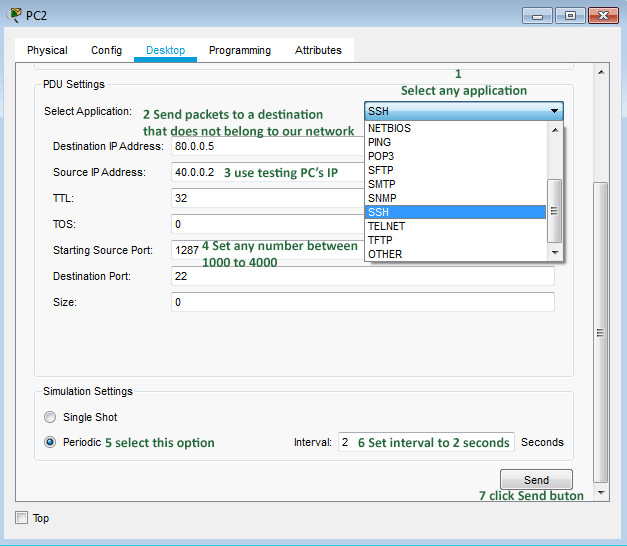
To verify the default route, click PC2, then Desktop, and then Traffic Generator.

In the PDU Settings section, adjust the settings as described below.
- Select any application, such as SSH, from the drop-down.
- In the "destination IP address" field, set an IP address that does not belong to available subnets configured in this network.
- In the "source IP address" field, fill in the IP address of the PC.
- In the "Starting source port" field, set any number from the range 1000 to 4000.
In the simulation settings section, select the Periodic radio button, set the Time interval to 2 seconds, and click the Send button.
If packets reach the log server, it verifies the default route configuration. The simulation panel in Packet Tracer displays real-time network events. When a device sends packets to another device in the network, this panel shows that transmission, including the complete path. Click the Simulation button in the bottom-right corner of Packet Tracer. In the Simulation pane, click the Start button.

As shown in the image above, packets sent by PC2 to an unknown host reached the log server. To stop the testing, open Traffic Generator on PC2 and click the Stop button. To hide the simulation panel, click the Realtime button at the bottom right of Packet Tracer.
The following link provides this lab with the above configuration.
Download the Packet Tracer lab with the default route configuration.
This tutorial is part of the tutorial series "Configure Default Routes in Cisco Router". Other parts of this series are the following.
Chapter 1 Default Routes in Cisco Routers Explained
Chapter 2 How to configure Default Routing in Cisco Routers
Chapter 3 Configure a Static Default Route in Cisco Packet Tracer
Chapter 4 How Gateway Router Propagates and Injects a Default Route
Conclusion
A router uses a default route to forward data packets going to a network not listed in the routing table. This tutorial explained how to configure, test, and verify a default route on Cisco routers through a Packet Tracer example.
Author Laxmi Goswami Updated on 2025-12-22