OSPF Neighborship Building Requirements and States Explained
Unlike other routing protocols, OSPF routers do not share routing information with all connected routers. They first build a neighborship and then share routing information only with neighbors. The entire process goes through the seven states. They use the first three states to build a neighborship. If a neighborship forms, they use the remaining four states to exchange routing information. This tutorial explains these states and the parameters that OSPF routers use to become neighbors.
Down state
In the down state, a router knows nothing about its neighbors. An OSPF process always starts in this state. In this state, it first selects a unique router ID. Routers use it to identify each other. It is a 32-bit numeric ID. It has the same format as an IP address uses in decimal notation.
After selecting the router ID, it sends Hello packets from all active interfaces and waits for a response from other OSPF routers. A Hello packet includes all the parameters that other OSPF routers need to determine whether they will form a neighborship with the sender router.

Init state
A router enters the init state when it receives a hello from a router that is not in its neighbour table. It compares the hello packet's parameters (explained later in this tutorial) with the locally configured. If both match, it replies. At this stage, communication is unidirectional.

Two-way state
A router enters the two-way state when it receives a reply from a router that is not in its neighbor list. This message informs the router that another router, which has added this router to its neighbor list, exists on the network.

If this router is willing to build a neighborship, it can reply with another Hello packet.

If the router replies, both routers enter the two-way state. If two routers reach this state, it means that both routers have met all OSPF configuration requirements to become neighbors.
At this point, they are neighbors and ready to exchange their routing information. They use the remaining steps to exchange the routing information. Once the routers have entered a two-way state, they are considered neighbors.
Network type
How routers will share routing information depends on the network type. In a broadcast multi-access network, they share routing information using DR and BDR. In a point-to-point network, they directly share routing information. In a broadcast multi-access network, they first elect the DR and BDR for the segment. A BDR is a hot standby for DR. If DR fails, it immediately becomes DR. Apart from the DR and BDR, all other routers in the segment are DROTHERs. DROTHERs exchange routing information only with DR. They do not share routing information directly. A DROTHER talks to a DR using the multicast address 224.0.0.6. DR and the BDR talk to DROTHERs using the 224.0.0.5 multicast address.
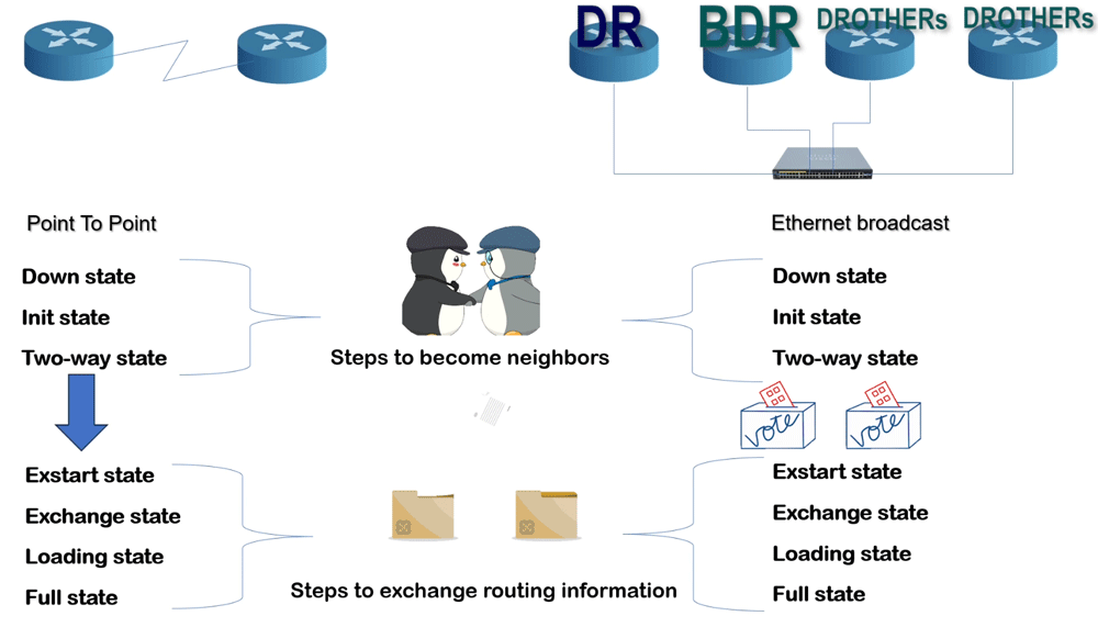
After building the neighborship, routers exchange routing information. For this, they use the remaining four states. In a point-to-point network, they immediately enter the Exstart state to initiate the exchange. In an Ethernet broadcast network, they first elect a DR and a BDR, then enter.
Exstrart state
After finalizing their roles, routers compare their router ID in each segment. A router with the highest router ID becomes the master. Remaining routers become the slaves. The master starts the routing information exchange process.

In this state, routers build adjacency. Adjacency allows directly connected routers to exchange routing information. In an Ethernet broadcast segment, DR builds adjacency with each DROther. Each adjacency contains two adjacent routers. The router with the highest router ID becomes the master and starts the exchange process by sharing its routing information. The remaining router becomes the slave and receives the routing update from the master in the exchange state.
Exchange state
Routers exchange routing information using LSAs. An LSA is a small portion of a database. It contains information only about a specific link. All routers maintain a database of LSAs. In the exchange state, they share a list of LSAs in their databases. Each LSA has a unique ID. Routers use it to check which LSAs they already have and then request only the LSAs they do not have from the other router.
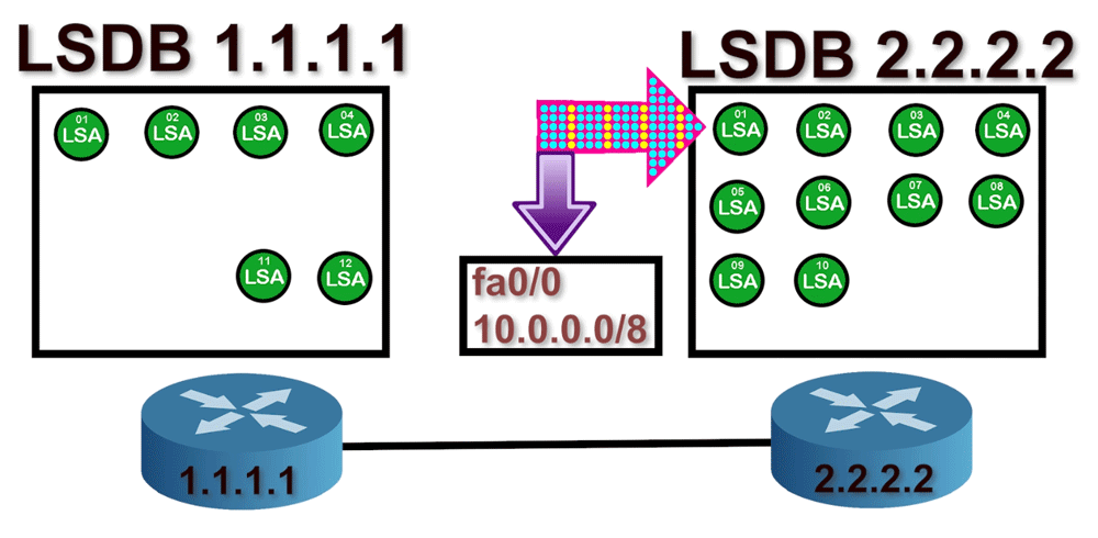
Let us take an example. The master sends a list of LSAs from its database to the slave. The list contains information about ten LSAs. The slave checks its database and finds four of those LSAs. Therefore, it will only request six LSAs using a Link-State Request packet. Similarly, the master compares the list it receives from the slave and requests the LSAs it does not have in its database.

Loading state
In the loading state, the master and slave provide the requested LSAs and incorporate the received LSAs into their respective databases. Then, they send an acknowledgment LSA to update each other.

Full state
Master and slave will repeat the exchange and loading steps until their databases are identical. Once the master and the slave are synchronized, you can consider them to be in a full state.

OSPF neighborship requirement
OSPF routers match five parameters to build neighborship. These parameters are Area ID, Hello and Dead Interval, Authentication, Stub flag, and MTU.
Area ID
OSPF uses areas to scale and optimize networks. OSPF areas serve as logical boundaries for routing information. By default, routers do not share routing information beyond their respective OSPF areas. Two routers become neighbors only if they are in the same area. An area covers only the router's interface, not the entire router. You can configure a single router to operate in multiple OSPF areas. For example, a router with a Serial interface and a FastEthernet interface can run the Serial interface in one area and the FastEthernet in another. To ensure that two routers are in the same area, the link connecting them must be in the same area, including the interfaces at both ends.

In the above network, R2 and R4 belong to different areas. They will not become neighbors. R1, R2, and R3 belong to the same OSPF area. They will check the remaining parameters to build a neighborship. Similarly, R4, R5, and R6 belong to the same OSPF area. They will also check the remaining parameters to form a neighborship.
Network ID
The Network ID is not an OSPF requirement for the neighborship. However, it directly affects the process of becoming a neighbor. A link comes up only when both end interfaces have IP addresses on the same subnet. If both end interfaces have IP configurations from different IP subnets, they cannot exchange IP packets. OSPF uses IP packets to share information between interfaces. If two interfaces cannot exchange IP packets, they cannot build an OSPF neighborship. In the following example, R2 and R3 belong to the same OSPF area. However, they cannot become neighbors. The link that connects them has an IP configuration from different subnets.
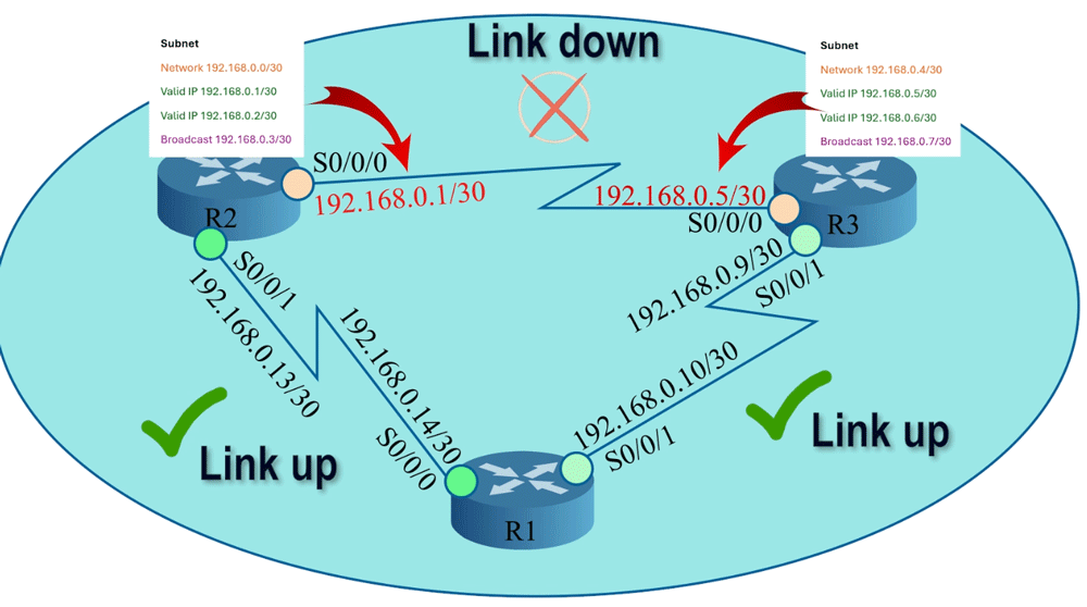
R2's serial 0/0/0 interface has an IP address from the subnet 192.168.0.0/30, while R3's serial 0/0/0 interface has an IP address from the subnet 192.168.0.4/30. To fix this issue, you must change the IP address of any of these interfaces. You can either change R2's serial 0/0/0 interface's IP address to 192.168.0.6/30 or R3's serial 0/0/0 interface's IP address to 192.168.0.2/30. After that, this link will come up.

Authentication
To enhance network security, OSPF allows you to configure the password for specific areas. Routers that have the same password will be eligible for neighborship. To use this facility, you must configure the password on all routers you want to include in the password-secured network. If you skip a router, the router will not join this network. When routers see each other's hello packets in the segment, they try to match all neighborship configuration values, including the password field. If the value of this field does not match, routers will ignore each other's packets.

Hello and Dead Interval
An OSPF router uses hello packets to discover and establish neighborship with other OSPF routers in the network. It sends hello packets at a specific interval. This interval is known as the hello interval. After building the neighborship, it uses hello packets to maintain the neighborship. The default hello interval is 10 seconds. It accepts a hello packet from the neighbor every 10 seconds. If it does not receive a hello packet in a hello interval, it waits for a specific period. This period is known as the dead interval. After the dead interval, it removes the router from the neighbor list. The default dead interval is 40 seconds. Two routers will become neighbors only when their hello and dead intervals match.

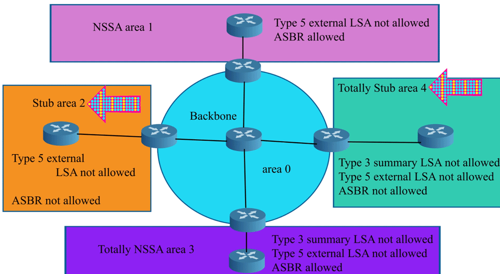
Stub flag
OSPF supports various types of areas to optimize the network, improve performance, and reduce the amount of routing information that routers exchange. A stub area is a special type of area. OSPF does not flood external networks in the stub areas. Routing from stub areas to the outside world is based on a default route. Stub area configuration reduces the size of the topology database and the memory requirements. A stub area has a single exit point. Two routers will become neighbors only when their stub area flags match.
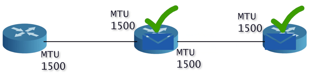
MTU
MTU is the maximum size of a data packet the interface can transport. Different interfaces can have different MTUs. It is an optional value. Routers can become neighbors even if their MTU values do not match. However, they will not be able to exchange routing updates.

For an error-free OSPF network, you must maintain this value consistently across all routers.
Video version
This tutorial is also available in video format. You can watch it to understand the concepts and configuration steps explained in this tutorial in more detail.

Conclusion
OSPF (Open Shortest Path First) uses a structured approach to establish neighborships and exchange routing information through a series of defined states. Starting from the Down state, where routers begin their journey, they progress through the Init and Two-way states to confirm their mutual willingness to form a neighborship. The type of network determines how this information is shared, specifically whether through a designated router (DR) in multi-access networks or directly in point-to-point settings.
The transition to the Exstart state allows routers to establish adjacency for information exchange. Subsequently, in the Exchange state, routers share their Link-State Advertisements (LSAs) to synchronize their databases. In the Loading state, they exchange the necessary LSAs. Finally, both routers reach the Full state, indicating a complete and successful exchange of routing information.
Understanding these states and the requirements for building OSPF neighborships is crucial for efficient routing and network stability. With this knowledge, you can effectively troubleshoot and optimize OSPF operations within your networks.
Author Laxmi Goswami Updated on 2025-11-25