Switching concepts explained with examples
An Ethernet switch learns MAC addresses of connected devices, stores them in the CAM table, uses the saved addresses to finalize the forwarding ports for incoming frames, and forwards them from selected ports. This tutorial explains key features associated with these functions through a Packet Tracer example.
Lab setup
Packet Tracer is network simulation software developed by Cisco for its certification program. It simulates essential Cisco devices. You can download the latest version of it from the following webpage.
Download Packet Tracer 9.0.0 and all Previous Versions
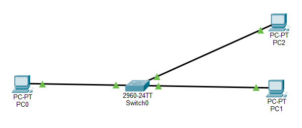
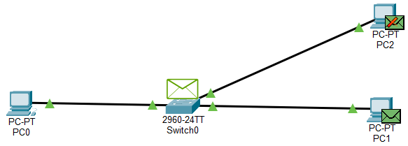
Add a switch to the workspace and three PCs to the workspace.
Connect these PCs to the switch in a sequence. Connect the first PC to the first Port, the second PC to the second port, and the third PC to the third port.
A PC needs an IP configuration to communicate with devices in the network. Assign an IP configuration from the same IP subnet to all PCs. It allows them to communicate with other PCs in the same subnet.
Pre-built lab to practice basic switch functions
Switching concepts
- A switch uses the source address field of the incoming frames to learn the MAC addresses of the connected devices.
- It saves the learned addresses in the CAM table and uses them to make the forwarding decisions.
- If you change a device port, the switch automatically updates the CAM entry associated with it.
- If a frame’s destination address is available in the CAM table, it forwards the frame only from the port or ports associated with that address in the CAM table entry.
- If a frame’s destination address is unavailable in the CAM table, it forwards the frame from all ports except the incoming port.
- It always forwards a frame having an unknown unicast, multicast, or broadcast address in the destination address field from all ports except the incoming port.
The following tutorial explains the above concepts in detail.
Basic Concepts of an Ethernet Switch
Testing and verifying switching concepts
You do not need any configuration on the switch to practice the switching concepts described in this tutorial. They are all part of the switch's default functionality. You can test and verify them with the default configuration. Access the switch's CLI interface. Enter Privilege Exec mode and run the show mac-address-table command to display the CAM table entries. Since this switch has not received any frames from its connected devices, its CAM table must be empty.
Switch>enable
Switch#show mac-address-table

As shown above, the CAM table has no entry. It verifies that a switch learns the MAC addresses of connected devices from the incoming frames it receives from them. Packet Tracer includes simulation mode. In this mode, it visualizes the real-time movement of frames. By default, this mode tracks all available protocols. Remove all protocols, then add ARP and ICMP.
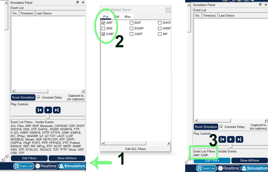
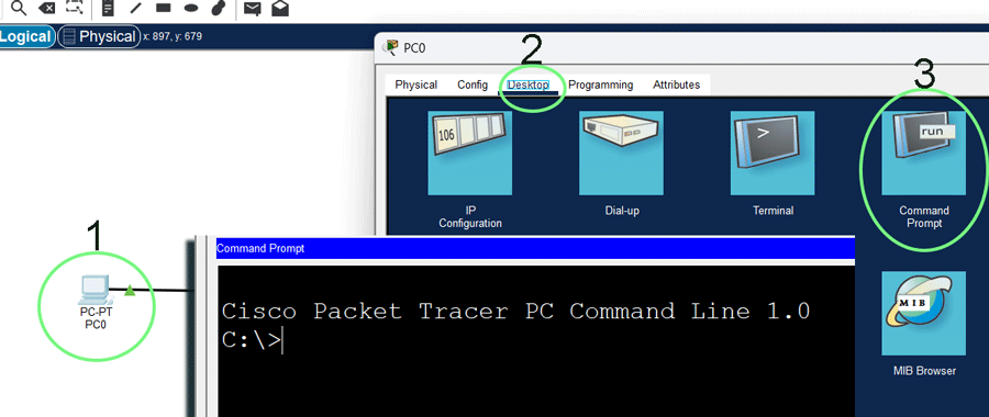
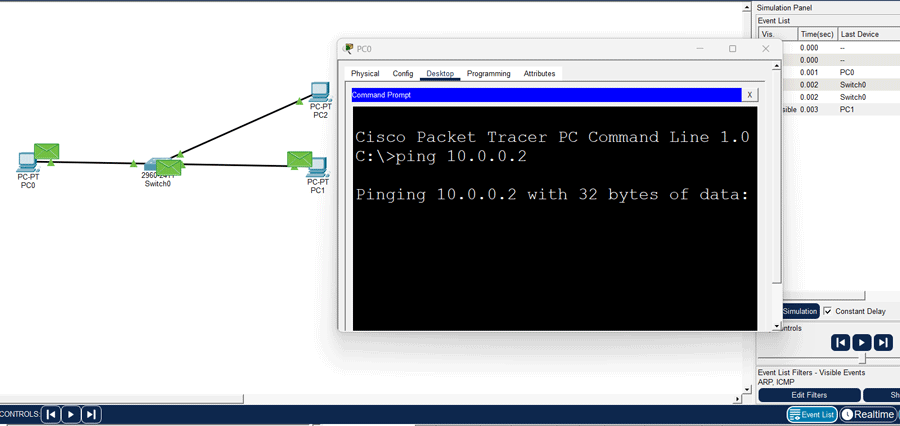
Devices use the ARP protocol to learn the MAC address of the destination IP address. ICMP provides the ping command. The ping command lets you test connectivity between the source and destination devices. Access the command prompt of the first PC.
The ping command needs the destination device's IP address as an argument. Specify the IP address of PC1. In simulation mode, you can control the frame's movement. Start the simulation.
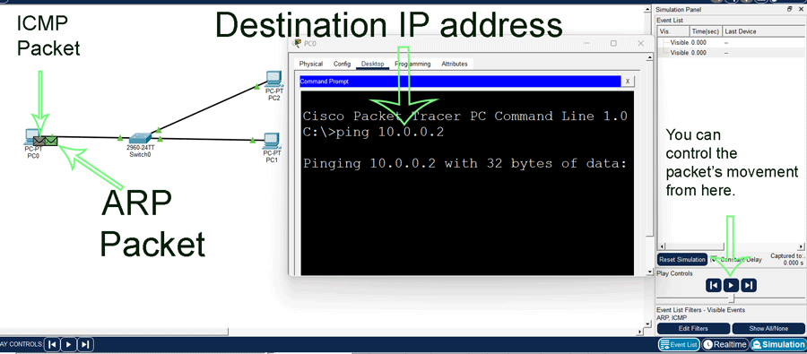
The source device needs both the IP and MAC addresses of the destination device before it can send data packets. It gets the destination device's IP address from the command prompt. However, it does not know its MAC address. To learn the MAC address of this device, it uses the ARP protocol.
The ARP protocol creates a local broadcast message for the device holding the specified IP address. This message requests the destination device to provide its MAC address. It includes the source device's MAC address in the source address field and the local broadcast address in the destination address field. The message reaches the switch on Port 1. Since the frame's destination address field has a local broadcast address, the switch forwards it from all active ports after adding PC0's MAC address from the source address field in the CAM table. Both PC1 and PC2 receive this message. PC2 ignores the message as its IP address does not match the recipient's IP address.
PC1's IP address matches the recipient's IP address. It replies to this message. Since it has already learned the sender device's MAC address from the source address field of the received broadcast message, it does not need to send the reply message to a local broadcast address. It can send it directly to the sender's device. In the source address field, it uses its MAC address, and in the destination address field, it uses the sender's device MAC address.
The reply message reaches the switch on Port 2. The switch reads the frame's destination address field and looks it up in its CAM table. The CAM table has an entry for the destination MAC address. This entry says the destination MAC address is available on Port 1. After adding PC1's MAC address from the frame's source address field, the switch forwards the frame out Port 1. The frame reaches PC0. From the reply message, PC0 learns PC1's MAC address. At this stage, it knows both the IP and MAC addresses of PC1.
After learning both addresses, the ping command sends data packets to PC1. Data packets reach the switch on Port 1. The switch reads the destination address field of packets. Since packets have a known unicast MAC address in the destination address field, they are forwarded only from the port associated with that MAC address. The same thing happens when it receives reply messages from PC2. It verifies that if a switch knows the destination MAC address of a frame, it forwards the frame only from the port connected to the destination device.

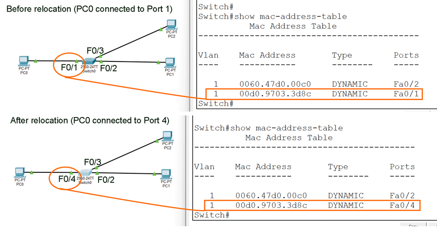
To verify that a switch dynamically updates MAC addresses in the CAM table, relocate PC0 from Port 1 to Port 4 and send ping requests again. Run the show mac-address-table command before and after the relocation.
Conclusion
Understanding switch concepts is fundamental for building and managing robust networks. Switches use MAC address learning and intelligent forwarding to ensure data is delivered efficiently to the correct destination. By leveraging techniques such as store-and-forward, cut-through, and fragment-free switching, you can optimize both performance and reliability. This tutorial explained the basic switch concepts through a Packet Tracer example. Mastery of these core switch concepts enables the design and maintenance of scalable, high-performing local area networks.
Author Laxmi Goswami Updated on 2025-12-21