Layer 2 and Layer 3 Switches Explained
In this tutorial, I will compare Layer 2 and Layer 3 switches, explain their roles and functions in computer networks, and list their differences. I will first provide a brief introduction to the layers. Then, I will describe the core functions of Layers 2 and 3 in the context of packet switching and forwarding. Later, I will explain what Layer 2 and Layer 3 switches are, how they work, and how they differ.
Introduction to layers
Layers are the logical classification of networking. They define how computers communicate and exchange data in a network. There are two popular layer models: OSI and TCP/IP. OSI defines seven layers: Application, Presentation, Session, Transport, Network, Data-Link, and Physical. TCP/IP specifies five layers: Application, Transport, Network, Data Link, and Physical. It merges the Presentation and Session layers into the Application layer.
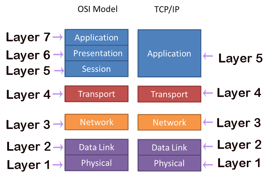
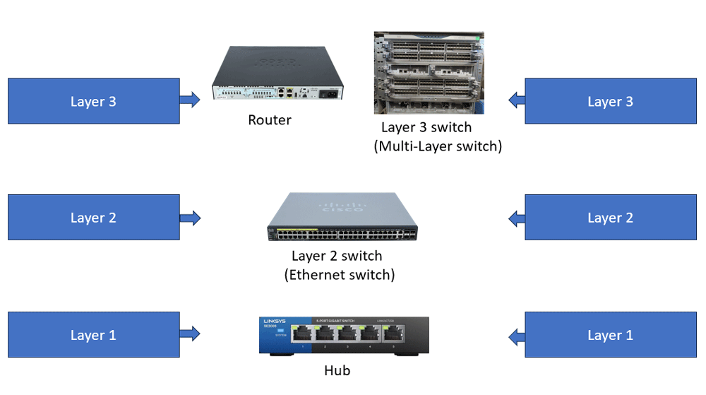
Each layer describes a particular part of the communication and defines rules and protocols only for the devices that operate at that layer and provide its features and functions. A device can operate in multiple layers. However, in that case, it must provide all features and functions of all layers it operates in and follow the rules and protocols defined for those layers. A device gets its title from the layer in which it operates. If it operates in multiple layers, it uses the title of the topmost layer. For example, if a device operates in layers 1 and 2, it is called a layer 2 device. Similarly, you can say that a layer 3 device operates at layers 1, 2, and 3.
A device provides all features and functions of its title layer and supports its protocols. For example, a layer 2 device supports layer 2 protocols and provides its features and functions. Historically, a switch was a layer 2 device. But in the past few years, major switch manufacturers have begun producing layer 3 switches. A layer 3 switch differs from a layer 2 switch. It is deployed in different scenarios.
Functions of a layer 2 switch
Layer 2 is called the Data Link layer. Frame switching occurs in this layer. A frame is a small piece of data that two devices exchange over a network. Each frame includes a source and a destination MAC address. The source MAC address belongs to the sender device, and the destination MAC address belongs to the receiver device. A MAC address is a hardware address. Every NIC (Network Interface Controller) has a unique MAC address stored in its ROM. This address provides a unique identity to the NIC on the local network. This address is not routable on the Internet or public network. It is significant only in a local network.
A layer 2 switch operates in this layer. It stores the MAC addresses of all connected devices in its MAC address table. When it receives a frame on its port, it reads the destination MAC address, looks it up in the MAC address table, and, if the table has an entry for the destination, forwards the frame from the port specified in that entry. If there is no entry for the destination address, it forwards the frame from all ports except the incoming port.
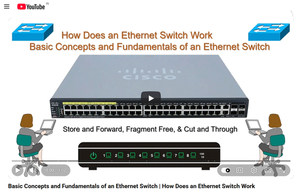
You can watch the following video to learn how an Ethernet switch works in the computer network.
Functions of a layer 3 switch
Layer 3 is called the Network layer. Packet forwarding occurs in this layer. A packet is a frame with a network-layer header. You can think of it as an envelope containing another envelope, with the inner envelope being a frame and the outer envelope a packet. Each packet contains a source and a destination IP address. The source IP address represents the sender device, and the destination IP address denotes the receiver device. An IP address is a software address. Every device on a network requires a unique IP address to communicate with others. You need to assign this address to every device. You can manually assign this address or configure the DHCP service. A DHCP service automatically assigns IP addresses to its clients. IP addresses are globally significant. You can access a device from anywhere using its IP address.
An IP address consists of two parts: network and host. The network address groups similar addresses. The host address provides a unique identity to the host system within the group defined by the network address. Devices with different network addresses in their IP addresses cannot communicate directly. They can communicate only through a router.
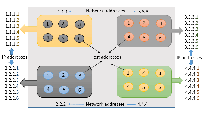
Devices sharing the same network address use broadcast messages to learn and share various information. A broadcast message generated in another network is meaningless for a device. A device never processes a broadcast message containing a network address that is different from its own.
Broadcast messages use layer 3 (IP) addresses in the destination address field. By default, a layer 2 switch does not understand layer 3 broadcast addresses and always forwards broadcast messages from all ports except the incoming port. It degrades network performance and causes numerous technical issues (such as a switching loop and an unstable MAC address table).
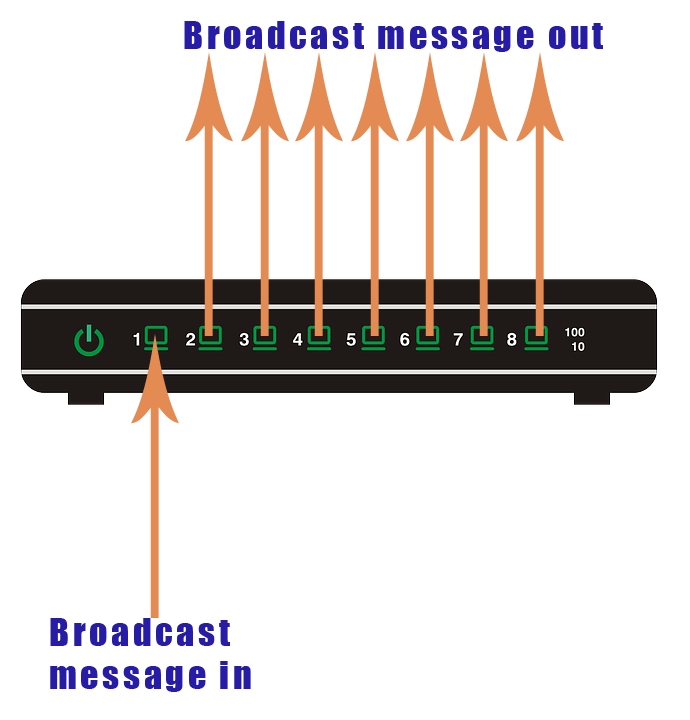
To handle these issues, layer 2 switches support a feature called VLANs. It allows you to define switch ports that belong to the same network. You create a VLAN and add all switch ports that belong to the same network to it. After that, a switch will forward broadcast messages only from the ports that belong to the same VLAN.
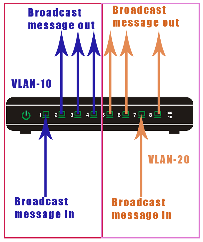
VLAN improves network performance and solves all related issues. However, it creates another issue. Devices in different VLANs cannot communicate directly. They can communicate only through a router.
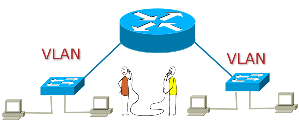
A router connects different VLANs. It stores the network addresses of all connected networks in its routing table. When it receives a packet on one of its interfaces, it reads the destination network address, looks it up in the routing table, and, if the table has an entry for the destination, forwards the packet from the interface specified in that entry. If there is no entry for the destination address, it discards the packet.
To connect different VLANs, you need to configure one Ethernet interface in each VLAN. Routers have only a few Ethernet interfaces. Mostly, routers have two or four Ethernet interfaces. Usually, these interfaces are not sufficient for all VLANs. To overcome this limitation, interface virtualization is used. It allows you to turn a physical interface into as many virtual interfaces as you want. After that, you can use virtual interfaces for VLANs. For example, if you have 10 VLANs. You can create 10 virtual interfaces and assign one virtual interface to each VLAN. Until a few years ago, this was the only solution for connecting different VLANs.
To learn how a router connects VLANs, you can watch the following video.
Routers are expensive. In addition to providing connectivity between different VLANs, they perform many other tasks. Using them solely to connect VLANs increases network costs and complicates management. To reduce network costs and simplify management, a new type of switch, called a layer 3 switch, was designed a few years ago. A layer 3 switch is basically a layer 2 switch that can connect different VLANs and has a few essential routing features.
A layer 3 swtich functions similarly to a router. However, it has more ports and processing power. It performs all the functions of a layer 2 switch, along with layer 3 routing. It operates at layers 2 and 3 and forwards packets based on its IP table. It assigns separate Ethernet ports (functions of layer 2 switches) to different VLANs and enables routing between them by supporting essential routing protocols, such as RIP and OSPF(functions of layer 3 routers). It implements several software-level functions that routers implement at the hardware level.
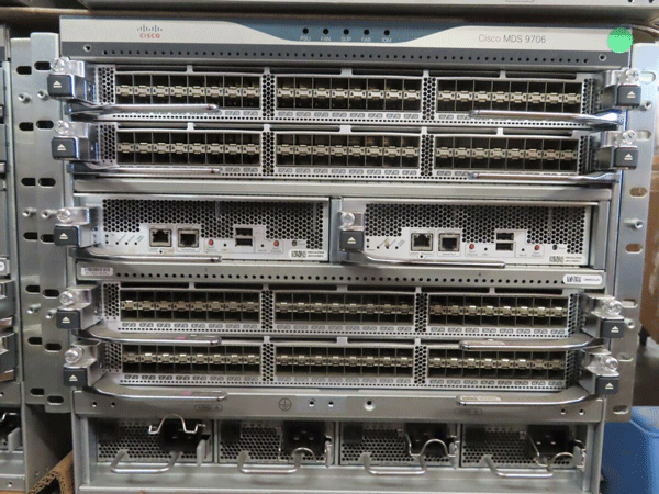
Although a layer 3 switch functions similarly to a router, it is not a replacement for a router. The following table compares and lists the differences between a router and a layer 3 switch.
Differences between a layer 3 switch and a router
| Layer 3 switch | Router |
| Allowing communication and data transfer between devices within and across the LANs and VLANs is the main function of a layer 3 switch. | Allowing communication and data transfer between different LANs and VLANs is the main function of a layer 3 switch. It is not used to allow communication between devices within a single LAN. |
| It does not support WAN. | It supports WAN as the main function. |
| It provides hardware-based switching. It can process and handle a large number of frames in a fraction of a millisecond. It is much faster than a router. | It provides software-based routing. Its processing and handling power is much slower than that of a layer 3 switch. |
| It supports a limited number of routing protocols. | It supports many routing protocols (such as OSPF, BGP, and EIGRP) for various requirements and scenarios. |
| It does not support edge technologies and advanced routing features. | It supports edge technologies, advanced routing, and security features such as firewalls, VPNs, and access control lists (ACLs). |
| It is less expensive than a router. | It is more expensive than a multilayer switch. |
| It does not offer complete routing capabilities. | It does not offer the switching benefits of layer 3 switches. |
Whether you should use a layer 3 switch or a router depends on your network type. If your network heavily uses VLANs and requires only a few essential routing features, you can use a layer 3 switch. It provides faster data transfer between different VLANs than a traditional router without increasing network traffic. However, if your network connects with external networks or needs more WAN functions, you should use a router.
Difference between a layer 2 and a layer 3 switch
| Layer 2 switch | Layer 3 switch |
| It processes frames based on the destination MAC address. | It processes frames based on the destination IP address. |
| It works in the Data-Link layer. | It works in the Network layer. |
| It cannot connect different VLANs. | It can connect VLANs. |
| It works as a single broadcast domain. | Based on the configuration, it can create multiple broadcast domains. |
| It does not support any routing protocol. | It supports essential routing protocols to provide intra-VLAN connectivity. |
| It is less expensive than the Layer 3 switch. | It is more expensive than the Layer 2 switch. |
This tutorial is part of the tutorial series 'Role and function of network components'. The other parts of this tutorial series are as follows.
Chapter 1.1.a Routers in Computer Networks Explained
Chapter 1.1.b Layer 2 and Layer 3 Switches Explained
Chapter 1.1.c Next-generation firewalls and IPS Explained
Chapter 1.1.d Access Points in Computer Networks Explained
Chapter 1.1.e Controllers in Computer Networks Explained
Chapter 1.1.f Endpoints in Computer Networks Explained
Chapter 1.1.g Servers in Computer Networks Explained
Chapter 1.1.h PoE in Computer Networks Explained
This tutorial series covers the following CCNA Exam v1.1 (CCNA 200-301) topics.
1.0 Network Fundamentals
- 1.1 Explain the role and function of network components
-
- 1.1.a Routers
- 1.1.b Layer 2 and Layer 3 switches
- 1.1.c Next-generation firewalls and IPS
- 1.1.d Access points
- 1.1.e Controllers
- 1.1.f Endpoints
- 1.1.g Servers
- 1.1.h PoE
Conclusion
A switch is an essential networking component. It comes in two variations: Layer 2 and Layer 3. In this tutorial, I compared the two variations, described their functions, and explained how they differ. By understanding the features and functions of both types, you can select the appropriate switch for your network.
Author Laxmi Goswami Updated on 2026-07-29