VLANs, VTP, and DTP Explained with Examples
VLANs are logical groups of devices on a local network. VTP (VLAN Trunk Protocol) and DTP (Dynamic Trunking Protocol) are protocols. VTP allows you to create and manage VLANs from a single switch. DTP enables switches to exchange VLAN information. This tutorial begins by explaining the fundamental concepts of VLANs, VTP, and DTP. Then, it covers how to create, configure, verify, and manage these technologies using a Packet Tracer example.
VLANs
A LAN is a group of devices connected to a single Ethernet network. A broadcast message is a message that reaches all devices in the LAN network. Devices use broadcast messages to perform many essential tasks. The more devices you add to a network, the more broadcast messages it will have. Broadcast messages reduce network performance. To improve network performance, you can break the LAN network into smaller LANs. When you break a large LAN into smaller LANs, you create VLANs. VLANs are smaller LANs. VLANs create a boundary for broadcast messages. A broadcast message generated in a VLAN reaches all devices inside the VLAN. It does not go outside the VLAN. If two devices belong to different VLANs, they do not exchange broadcast messages.
How VLANs work
A switch does not understand broadcast messages. When it receives a broadcast message on one of its ports, it forwards that message to all devices connected to the remaining ports. For example, an 8-port switch receives a broadcast message on port 1. It forwards the message from port 2 to 8.

A VLAN is a switch-only feature. It allows you to define ports that share broadcast messages. If two switch ports belong to different VLANs, they do not share broadcast messages. They share broadcast messages only if they belong to the same VLAN. In the preceding example, if you create two VLANs: VLAN-10 and VLAN-20 on the Switch and assign ports 1 to 4 to VLAN-10 and ports 5 to 8 to VLAN-20, then ports 1, 2, 3, and 4 will share broadcast in VLAN-10, and ports 5, 6, 7, and 8 will share broadcast in VLAN-20.

VLANs are not limited to a standalone switch. You can create and use them across multiple switches. This feature allows you to organize your network logically. Let us take one more example. A network has three segments. Each segment has four PCs.

Suppose you want to break this network into three sections: Development, Production, and Administration. In the Development section, you want to keep six computers, two from each segment. In the Production section, you want to put three computers, one from each segment. You have a similar requirement for the Administration section: one computer from each segment. In this situation, you can use VLANs. VLANs allow you to create logical groups of devices. You can create three VLANs, one for each section. You must create these VLANs on all switches. After creating VLANs, you can add computers to their respective VLANs. VLANs are similar to network segments. Devices in different VLANs cannot communicate directly. You must connect them through a router.

Key points:-
- VLANs are a switch-only feature. It works only on manageable Ethernet switches.
- VLANs create boundaries for broadcast messages.
- VLANs do not share broadcast messages.
- Devices in different VLANs cannot communicate directly. They can communicate through a router.
- You can create and use the same VLAN on multiple routers. This feature allows you to arrange devices logically.
- All switches have a default VLAN, called VLAN1.
- By default, all switch ports belong to VLAN1.
VTP
If you want to use the same VLANs across multiple switches, you must create them on all switches. If your network is small, you can manually manage VLANs. For example, if your network has only two switches and you want to add a new VLAN, you can easily add that VLAN to both switches. However, if your network has 50 switches, this process becomes complex and tedious. You might forget to add the new VLAN to one of these switches.
VTP solves this issue. It allows you to manage VLAN information from a single switch. With it, you need to add or remove VLAN information only on the VTP Server. VTP Server automatically propagates the new VLAN information, via VTP messages, to all of the other switches in the network. VTP shares VLAN configuration information between Cisco switches on trunk connections. It allows switches to share and synchronize their VLAN information, ensuring the network has a consistent VLAN configuration.
VTP domains
A VTP domain is a group of switches that share VTP information. For example, you have 50 switches in a network. You want only 30 of them to share VTP information. In that case, you can keep them in a VTP domain. If a switch is not a member of a VTP domain, it ignores VTP messages shared in that domain.

A switch can belong only to a single domain. When switches generate VTP messages, they include the domain name in their messages. A switch processes an incoming VTP message only when the domain name in the message and the domain name configured on it are the same.
VTP modes
There are three VTP modes: Server, Transparent, and Client. Based on the mode you configure on a switch, the Switch interacts with VLANs.
VTP Server mode
This mode allows you to add, modify, and delete VLANs. It automatically propagates VLAN information to other switches. You can configure multiple VTP Server switches in a VTP domain. If a VTP Server receives VLAN information from another VTP Server in the same VTP domain, it compares the received information with the locally saved information and keeps the updated information. To compare information, it uses the configuration revision number. VTP Server adds a configuration revision number to each VLAN information it advertises through VTP messages.

Initially, this number is zero (0). When you make a change on a Server switch, it increments its revision number and advertises this to the other switches. When a Client or other Server switch receives this information, it compares the revision number in the message to the last message it received. If the newly arrived message has a higher number, it assumes that the VLAN information on the Server has changed and updates the locally stored information from the received message. If the message has the same revision number, it ignores the message.
VTP Client mode
In this mode, a switch depends on the VTP Server for VLAN information. It can not make any change in the VLAN information itself. It incorporates VTP messages received from the VTP Server and implements the VLANs as specified in the VTP messages.
VTP Transparent mode
In this mode, a switch acts as a bridge between the VTP Server and the VTP Clients. It connects VTP Servers with VTP Clients. It forwards the messages it receives from the VTP Server to the VTP Clients. It does not change or incorporate VTP messages. You can add, modify, and delete VLAN on a Transparent switch. But these changes are locally significant. It does not forward them to other switches.
Access and Trunk ports
A switch port can work in two modes: access and trunk. In access mode, it is called an access port. In trunk mode, it is called a trunk port. An access port works only with a single VLAN. It forwards all incoming frames from the ports that belong to the VLAN configured on it. A device attached to an access port does not understand the VLAN concept. It assumes the connected link and network as a single broadcast domain. Switches remove all VLAN information from frames before forwarding them through access ports. A trunk port works with multiple VLANs. It adds VLAN information to frames before forwarding them. Since it attaches VLAN information to frames, the device connected to it must understand VLAN concepts. You can attach a switch or a router to a trunk port in a multi-VLAN environment.
VLAN Tagging
A trunk port adds VLAN information to each frame before forwarding it. This process is called VLAN tagging. The switch connected to another side of the trunk port uses the attached information to identify the VLANs of the frames.

DTP
A DTP protocol dynamically manages trunk connections. Based on the connected device, it automatically changes the switch port's mode. For example, if the connected device is a switch, it changes the port's mode to trunk mode. If the connected device is a PC or Server, it changes the port's mode to access mode. It supports five modes: On or Trunk, Desirable, Auto, Off, and No-Negotiate.
On or Trunk mode
In On or Trunk mode, it assumes the remote port is a trunk port. It starts the local port in trunk mode and keeps it in this mode. It generates DTP messages and adds VLAN information to frames. If the remote port is an access port, this mode can block all communication between both ports.
Desirable mode
In Desirable mode, it starts the local port in access mode. It generates DTP messages and sends them to the remote port. If the remote port replies to DTP messages, it assumes the remote port is a trunk port and changes the local port's mode to trunk mode. If the remote port does not reply to DTP messages, it assumes the remote port is an access port and keeps the local port in access mode.
Auto mode
In Auto mode, it starts the local port in access mode and passively listens for DTP messages from the remote side. If it receives a DTP message from the remote port, it assumes the remote port is a trunk port and changes the local port's mode to trunk mode. It is the default mode on trunk-capable ports on Cisco switches.
No-negotiate
In No-negotiate mode, it starts the local port in trunk mode and adds VLAN information to frames. In this mode, it does not generate and send DTP messages. DTP is a Cisco proprietary protocol. It works only on Cisco switches. If you connect a Cisco switch to a non-Cisco switch, the non-Cisco Switch will not understand DTP messages. In that situation, you can use this mode.
Off
In off mode, it starts the local port in access mode and keeps it in this mode all the time. In this mode, it neither generates DTP messages nor adds VLAN information to frames.
VLANs, VTP, and DTP configurations
To explain configuration steps and commands, this tutorial uses Packet Tracer network simulator software. You can download Packet Tracer from the following link.
Download Packet Tracer 8.2.2 and all Previous Versions
Create a Packet Tracer lab as shown in the following image.

Alternatively, you can download the prebuilt lab from the following link.
VLANs, VTP, and DTP Practice Lab - Without Configuration
This lab contains six PCs, three Switches, and one Router. All PCs have an IP configuration as shown in the image. Apart from it, all devices have default configurations.
Objectives:-
- Create a VLAN on the first Switch.
- Configure the first Switch as a VTP Server, the second Switch as a VTP Transparent, and the third Switch as a VTP Client.
- Configure DTP on ports connecting switches.
- Verify that the VTP Client switch receives VLAN configuration from the VTP Server.
- Verify that the VTP Transparent switch does not save the VLAN configuration it receives from the VTP Server.
- Add a VLAN on the VTP Server switch.
- Check the VTP Client and verify that it receives the VLAN added on the VTP Server switch.
- Add the same VLANs on the VTP Transparent switch.
- Assign VLANs to interfaces.
- Verify that devices inside the VLAN can communicate.
- Verify that devices cannot communicate with devices outside the VLAN.
- Configure Router-on-Stick on the router.
- Verify Intra-VLAN connectivity.
Creating a VLAN on the first Switch
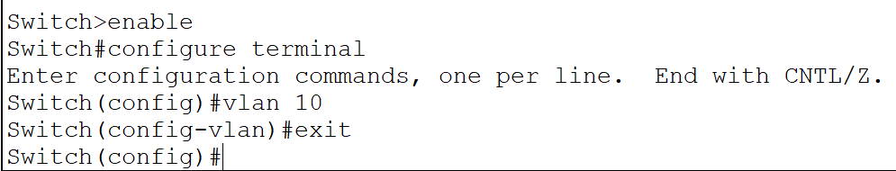
Access the CLI interface of the first Switch and run the following commands.
| Command | Description |
| Switch>enable | Enter privileged-exec mode |
| Switch#configure terminal | Enter global configuration mode |
| Switch(config)#vlan 10 | Create a VLAN and enter VLAN configuration mode |
| Switch(config-vlan)#exit | Exit VLAN configuration mode |
- You can add a new VLAN or manage an existing VLAN only in global configuration mode.
- The vlan [name or number of the VLAN] command checks the specified name or number for an existing VLAN. If a VLAN with the same name or number exists, it enters the VLAN configuration mode of that VLAN. If not, it creates a new VLAN and enters the VLAN configuration mode for that VLAN.
- VLAN configuration mode allows you to configure additional properties for the VLAN. These properties are optional and usually not required.
Configuring VTP
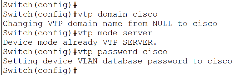
Run the following commands in global configuration mode of the first Switch.
| Command | Description |
| Switch(config)#vtp domain cisco | Create a VTP domain |
| Switch(config)#vtp mode server | Change VTP mode to Server |
| Switch(config)#vtp password cisco | Set VTP domain password |
- VTP shares VLAN information within the domain.
- A switch can join a VTP domain only if it knows the correct password.
- VTP Server shares VLAN information in the VTP domain.
Run the following commands on the second Switch to make it a VTP Transparent switch.
| Command | Description |
| Switch>enable | Enter privileged-exec mode |
| Switch#configure terminal | Enter global configuration mode |
| Switch(config)#vtp domain cisco | Join the specified VTP domain |
| Switch(config)#vtp mode transparent | Change VTP mode to Transparent |
| Switch(config)#vtp password cisco | Use the given password to join the VTP domain |

A VTP Transparent switch receives VLAN information from the VTP Server and passes it to connected switches.
Run the following commands on the third Switch to make it a VTP Client switch.
| Command | Description |
| Switch>enable | Enter privileged-exec mode |
| Switch#configure terminal | Enter global configuration mode |
| Switch(config)#vtp domain cisco | Join the specified VTP domain |
| Switch(config)#vtp mode client | Change VTP mode to Client |
| Switch(config)#vtp password cisco | Use the given password to join the VTP domain |

A VTP Client receives VLAN information from the VTP Server.
Configuring DTP
Run the following commands on the first Switch.
| Command | Description |
| Switch(config)#interface GigabitEthernet 0/1 | Enter interface configuration mode. This port connects it to the router. |
| Switch(config-if)#switchport mode trunk | Change the switchport mode to trunk. |
| Switch(config-if)#exit | Exit interface configuration mode. |
| Switch(config)#interface GigabitEthernet 0/2 | Enter interface configuration mode. This port connects it to the second Switch. |
| Switch(config-if)#switchport mode trunk | Change the switchport mode to trunk. |
| Switch(config-if)#exit | Exit interface configuration mode. |

By default, all switch ports work in access mode. In access mode, a switch port removes VLAN information from frames before forwarding them to the connected device. In trunk mode, it adds VLAN information to outgoing frames and removes VLAN information from incoming frames.
Run the following commands on the second Switch.
| Command | Description |
| Switch(config)#interface GigabitEthernet 0/1 | Enter interface configuration mode. This port connects it to the third Switch. |
| Switch(config-if)#switchport mode trunk | Change the switchport mode to trunk. |
| Switch(config-if)#exit | Exit interface configuration mode. |
| Switch(config)#interface GigabitEthernet 0/2 | Enter interface configuration mode. This port connects it to the first Switch. |
| Switch(config-if)#switchport mode trunk | Change the switchport mode to trunk. |
| Switch(config-if)#exit | Exit interface configuration mode. |
Run the following commands on the third Switch.
| Command | Description |
| Switch(config)#interface GigabitEthernet 0/1 | Enter interface configuration mode. This port connects it to the second Switch. |
| Switch(config-if)#switchport mode trunk | Change the switchport mode to trunk. |
| Switch(config-if)#exit | Exit interface configuration mode. |

Verifying VTP and DTP
You can verify VTP and DTP by checking VLAN information on the second and third Switches. The second Switch receives it from the first Switch and passes it to the third Switch. The third Switch receives it from the second Switch. Run the following commands on the second Switch in privileged-exec mode.
#show vlan

#show vtp status

The second Switch is a Transparent switch. A Transparent switch does not save the VLAN information it receives from the VTP Server. It only passes that information to other switches.
Run the following commands on the third Switch in privileged-exec mode.
#show vlan

#show vtp status

The third Switch is a Client switch. It uses the VLAN information it receives from the VTP Server.
Managing VLANs from a VTP Server
VTP allows you to manage VLANs from the VTP Server. VTP Clients replicate the changes you make on the VTP Server. For example, if you add a new VLAN or remove an existing VLAN on the VTP Server, the change automatically propagates to VTP Clients. To verify this, add a new VLAN on the VTP Server and check the VLAN configuration on the VTP Client. Run the following command on the first Switch.
Switch(config)#vlan 20
Switch(config-vlan)#exit
Switch(config)#

Run the following command on the third Switch.
Switch#show vlan

Adding VLANs on a Transparent switch
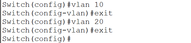
Since a Transparent switch can not save and use the VLAN information it receives from the VTP Server, you must manually create and manage VLANs on it. Create the same VLANs on the second Switch.
Switch(config)#vlan 10
Switch(config-vlan)#exit
Switch(config)#vlan 20
Switch(config-vlan)#exit
Switch(config)#
Assigning VLANs to interfaces
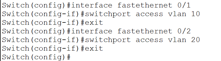
A VLAN works only when you assign it to a port. Run the following commands on the first Switch.
Switch(config)#interface fastethernet 0/1
Switch(config-if)#switchport access vlan 10
Switch(config-if)#exit
Switch(config)#interface fastethernet 0/2
Switch(config-if)#switchport access vlan 20
Switch(config-if)#exit
Switch(config)#
The switchport access vlan [vlan_ID] command assigns the specified VLAN to the interface.
Run the following commands on the second Switch.
Switch(config)#interface fastethernet 0/1
Switch(config-if)#switchport access vlan 10
Switch(config-if)#exit
Switch(config)#interface fastethernet 0/2
Switch(config-if)#switchport access vlan 20
Switch(config-if)#exit
Switch(config)#
Run the following commands on the third Switch.
Switch(config)#interface fastethernet 0/1
Switch(config-if)#switchport access vlan 10
Switch(config-if)#exit
Switch(config)#interface fastethernet 0/2
Switch(config-if)#switchport access vlan 20
Switch(config-if)#exit
Switch(config)#
Verifying VLANs
To verify the VLAN configuration, you can test connectivity between the PCs. If a PC can access another PC on the same VLAN but cannot access a PC on a different VLAN, it verifies the VLAN configuration. Send ping requests from the first PC to the third and fifth PCs. All three PCs belong to VLAN-10. If they have connectivity, it verifies the configuration you made.

To verify that PCs in different VLAN cannot communicate, send ping requests from the first PC to the second, fourth, and sixth PCs.

Router-on-stick configuration
Devices on different VLAN can communicate only through a router. Ethernet ports connect VLANs to the router. You need one Ethernet port for each VLAN. Routers have limited Ethernet ports. Usually, a router has two or four Ethernet ports. On the other side, a typical network may have several VLANs. For these, you need many Ethernet ports. Virtualization solves this issue. It turns a physical Ethernet port into multiple virtual Ethernet ports. Each virtual Ethernet port works as a separate port. When you convert a physical port into virtual ports and use them to connect VLANs, it is called a router-on-stick configuration. Run the following commands on the router.
| Command | Description |
| Router>enable | Start privileged-exec mode |
| Router#configure terminal | Enter global configuration mode |
| Router(config)#interface fastethernet 0/0 | Access interface configuration mode of the interface Fastethernet 0/0 |
| Router(config-if)#no ip address | Remove IP configuration from the physical interface |
| Router(config-if)#no shutdown | Start the physical interface and keep it running |
| Router(config-if)#exit | Exit the interface configuration mode |
| Router(config)interface fastethernet 0/0.10 | Create a virtual interface (0/0.10) and enter sub-interface configuration mode |
| Router(config-subif)#encapsulation dot1Q 10 | Change the default encapsulation to dot1Q for VLAN-10 |
| Router(config-subif)#ip address 10.0.0.1 255.0.0.0 | Assign the IP address 10.0.0.1 255.0.0.0 |
| Router(config-subif)#exit | Exit the sub-interface configuration mode |
| Router(config)interface fastethernet 0/0.20 | Create a virtual interface (0/0.20) and enter sub-interface configuration mode |
| Router(config-subif)#encapsulation dot1Q 20 | Change the default encapsulation to dot1Q for VLAN-20 |
| Router(config-subif)#ip address 20.0.0.1 255.0.0.0 | Assign the IP address 20.0.0.1 255.0.0.0 |
| Router(config-subif)#exit | Exit the sub-interface configuration mode |
| Router(config)# | Global configuration mode |

Verifying router-on-stick configuration
To verify the router-on-stick configuration, you can test connectivity between devices of the different VLANs. Send ping requests from the first PC to the second PC. Both PCs belong to other VLANs.

You can download the configured lab from the following link.
VLANs, VTP, and DTP Practice Lab - With Configuration
Conclusion
This tutorial explained basic concepts, fundamentals, and configuration steps of VLANs, VTP, and DTP. Learning these helps you manage your network effectively.
Author Laxmi Goswami Updated on 2026-04-14