Configure DHCP Server for multiple VLANs on the Switch
VLAN is a switch feature. It creates a group of devices that share broadcast messages in a local network. A broadcast message generated in one VLAN does not reach another VLAN. DHCP service relies on broadcast messages. DHCP clients use broadcast messages to send DHCP requests. A DHCP server provides an IP configuration only when it receives a DHCP request from a DHCP client. If you configure a DHCP server on one VLAN and its clients on another VLAN, requests from DHCP clients to obtain an IP configuration never reach the DHCP server. Since it does not receive DHCP requests, it does not provide IP configurations. It can provide IP addresses only when it receives DHCP request messages from clients.
However, it does not mean you need a separate DHCP server for each VLAN. It means you need to set up your network so that DHCP requests from DHCP clients reach the DHCP server. For example, you can configure all devices that separate VLAN traffic to allow DHCP messages, or configure the DHCP service on the switch where you created VLANs, or on the router that provides connectivity between VLANs. This tutorial explains the second option. The first and third options are explained separately in other tutorials of this tutorial series.
This tutorial is part of the tutorial series "DHCP (Dynamic Host Configuration Protocol) basic concepts, configurations, functions, and options explained". Other parts of this series are the following.
Chapter 1 What DHCP is and Types of DHCP Explained
Chapter 2 How DHCP works explained with examples
Chapter 3 DHCP Configuration Parameters and Settings Explained
Chapter 4 How to Configure DHCP Server on Cisco Switches
Chapter 5 Configure DHCP Server for multiple VLANs on the Switch
Chapter 6 How to Configure DHCP Server on Cisco Routers
Chapter 7 How DHCP Relay Agents work Explained
Chapter 8 How to Configure DHCP Relay Agent on Cisco Routers
Chapter 9 How DHCP Snooping works Explained
Chapter 10 Configure DHCP Snooping on Cisco Switches
Lab setup
Set up a practice lab as shown in the following image. You can use any network simulator software of your choice or use real Cisco devices. DHCP configuration steps and commands are the same on all platforms. This tutorial uses Packet Tracer. It also provides download links to the lab used in this tutorial, including the initial and full configurations.
Practice lab with the initial configuration

Video version
This tutorial is also available as a video on our YouTube channel. Use the link below to access the video and see a step-by-step demonstration of the concepts and configuration procedures discussed in this tutorial.
Configure a DHCP Server for multiple VLANs
VLANs and IP subnets
An IP subnet defines a layer three boundary for devices. Devices in one IP subnet can reach devices in another IP subnet only through a router. Subnets also create boundaries for broadcast messages. Broadcast messages are sent to broadcast addresses. Every IP subnet has a unique broadcast address. A device listens only to the broadcast address of its own IP subnet. It never processes a broadcast message from another IP subnet. However, it checks each received broadcast message to know whether it belongs to it. If it belongs to its own IP subnet, it processes the message. If not, it discards the message.
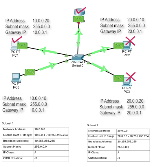
If you set up your network so that devices receive broadcast messages only from their own IP subnet, your network performance will improve drastically. VLANs help you achieve this goal. Without VLANs, a switch forwards a broadcast message from all ports except the port on which it arrived. If you use a switch without VLANs, all connected devices will receive broadcast messages from all IP subnets. If you configure VLANs, only devices on the same VLAN receive broadcast messages. You need to configure one VLAN for each IP subnet. For example, if your network uses two IP subnets, you need two VLANs.

VLAN configuration on the switch
Create two VLANs and assign the first VLAN to the ports connected to the first two PCs, and the second VLAN to the remaining two PCs. The vlan command in Global configuration mode creates a VLAN. It needs a VLAN ID as an argument. The switchport access vlan command in Interface configuration mode assigns the specified VLAN to the interface. Devices in different VLANs cannot communicate directly. They can communicate only through a router. A router provides connectivity between different VLANs only when it receives traffic from all of them. By default, all switch ports operate in access mode. In access mode, a switchport receives and forwards traffic for only one VLAN. To forward traffic from all VLANs to the router, change the switchport mode to trunk on the port connecting the switch to the router. The switchport mode trunk command changes the default port mode to trunk.
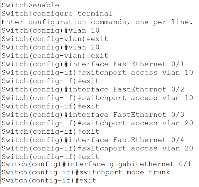
Access the switch's CLI prompt and run the following command.
Switch>enable
Switch#configure terminal
Switch(config)#vlan 10
Switch(config-vlan)#exit
Switch(config)#vlan 20
Switch(config-vlan)#exit
Switch(config)#interface fastethernet 0/1
Switch(config-if)#switchport access vlan 10
Switch(config-if)#exit
Switch(config)#interface fastethernet 0/2
Switch(config-if)#switchport access vlan 10
Switch(config-if)#exit
Switch(config)#interface fastethernet 0/3
Switch(config-if)#switchport access vlan 20
Switch(config-if)#exit
Switch(config)#interface fastethernet 0/4
Switch(config-if)#switchport access vlan 20
Switch(config-if)#exit
Switch(config)#interface gigabitethernet 0/1
Switch(config-if)#switchport mode trunk
Switch(config-if)#exit
Switch(config)#
| Command | Description |
| Switch>enable | Enter Privilege Exec mode. |
| Switch# configure terminal | Enter Global configuration mode. |
| Switch(config)# vlan 10 | Create VLAN-10 and enter VLAN configuration mode. |
| Switch(config-vlan)#exit | Exit VLAN configuration mode. |
| Switch(config)# vlan 20 | Create VLAN-20 and enter VLAN configuration mode. |
| Switch(config-vlan)#exit | Exit VLAN configuration mode. |
| Switch(config)#interface FastEthernet 0/1 | Enter interface configuration mode for FastEthernet 0/1. |
| Switch(config-if)#switchport access vlan 10 | Assign VLAN-10 to FastEthernet 0/1. |
| Switch(config-if)#exit | Exit interface configuration mode. |
| Switch(config)#interface FastEthernet 0/2 | Enter interface configuration mode for FastEthernet 0/2. |
| Switch(config-if)#switchport access vlan 10 | Assign VLAN-10 to FastEthernet 0/2. |
| Switch(config-if)#exit | Exit interface configuration mode. |
| Switch(config)#interface FastEthernet 0/3 | Enter interface configuration mode for FastEthernet 0/3. |
| Switch(config-if)#switchport access vlan 20 | Assign VLAN-20 to FastEthernet 0/3. |
| Switch(config-if)#exit | Exit interface configuration mode. |
| Switch(config)#interface FastEthernet 0/4 | Enter interface configuration mode for FastEthernet 0/4. |
| Switch(config-if)#switchport access vlan 20 | Assign VLAN-20 to FastEthernet 0/4. |
| Switch(config-if)#exit | Exit interface configuration mode. |
| Switch(config)#interface GigabitEthernet 0/1 | Enter interface configuration mode for GigabitEthernet 0/1. |
| Switch(config-if)#switchport mode trunk | Change switchport mode to trunk. |
| Switch(config-if)#exit | Exit interface configuration mode. |
That’s all the configuration you need on the switch.
Enabling connectivity between VLANs
A router interface works as a gateway device for an IP subnet. To connect two IP subnets or VLANs, you need two router interfaces. Routers have limited interfaces. Using a separate physical interface for each VLAN is generally not possible. Rather than using a physical interface for every VLAN, you can enable virtualization on a physical interface and create as many virtual interfaces as you need. You need only two commands to enable virtualization on an interface. These commands are no shutdown and no IP address. Run these commands in interface configuration mode on the interface that receives VLAN traffic. Creates two virtual interfaces, one for each VLAN. Assign the first virtual interface to the first VLAN and the second virtual interface to the second VLAN. For this, set the default encapsulation type to Dot1Q and provide the VLAN ID as an argument. These interfaces will work as the gateway devices for their respective VLANs. Assign the IP address you configured as the default Gateway IP address on the PCs of the first VLAN to the first interface and the gateway IP address of the second VLAN to the second interface. Routers automatically extract routing information from the IP addresses you assign to their interfaces and add it to the routing table. You can verify it by listing the routing table entries.
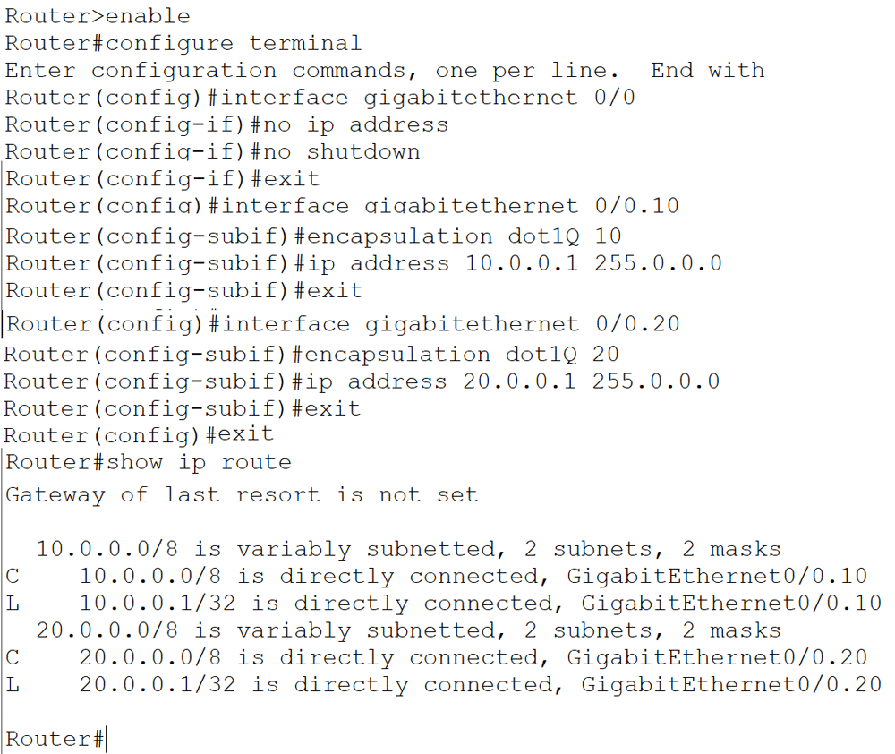
Access the router's CLI prompt and run the following commands.
Router>enable
Router#configure terminal
Enter configuration commands, one per line.  End with CNTL/Z.
Router(config)#interface gigabitethernet 0/0
Router(config-if)#no ip address
Router(config-if)#no shutdown
Router(config-if)#exit
Router(config)#interface gigabitethernet 0/0.10
Router(config-subif)#encapsulation dot1Q 10
Router(config-subif)#ip address 10.0.0.1 255.0.0.0
Router(config-subif)#exit
Router(config)#interface gigabitethernet 0/0.20
Router(config-subif)#encapsulation dot1Q 20
Router(config-subif)#ip address 20.0.0.1 255.0.0.0
Router(config-subif)#exit
Router(config)#exit
Router#show ip route
| Command | Description |
| Router>enable | Enter Privilege Exec mode. |
| Router#configure terminal | Enter Global configuration mode. |
| Router(config)#interface gigabitethernet 0/0 | Enter Interface configuration mode for GigabitEthernet 0/0. |
| Router(config-if)#no ip address | Remove the IP configuration (allow you to create virtual interfaces on this interface) |
| Router(config-if)#no shutdown | Enable the interface. |
| Router(config-if)#exit | Exit Interface configuration mode. |
| Router(config)#interface gigabitethernet 0/0.10 | Create a virtual interface and enter Interface configuration mode. |
| Router(config-subif)#encapsulation dot1Q 10 | Attach VLAN 10 to this interface. |
| Router(config-subif)#ip address 10.0.0.1 255.0.0.0 | Assign the IP address 10.0.0.1 to this interface. |
| Router(config-subif)#exit | Exit interface configuration mode. |
| Router(config)#interface gigabitethernet 0/0.20 | Create a virtual interface and enter Interface configuration mode. |
| Router(config-subif)#encapsulation dot1Q 20 | Attach VLAN 20 to this interface. |
| Router(config-subif)#ip address 20.0.0.1 255.0.0.0 | Assign the IP address 20.0.0.1 to this interface. |
| Router(config-subif)#exit | Exit Interface configuration mode. |
| Router(config)#exit | Exit Global configuration mode. |
| Router#show ip route | Display routing table entries |
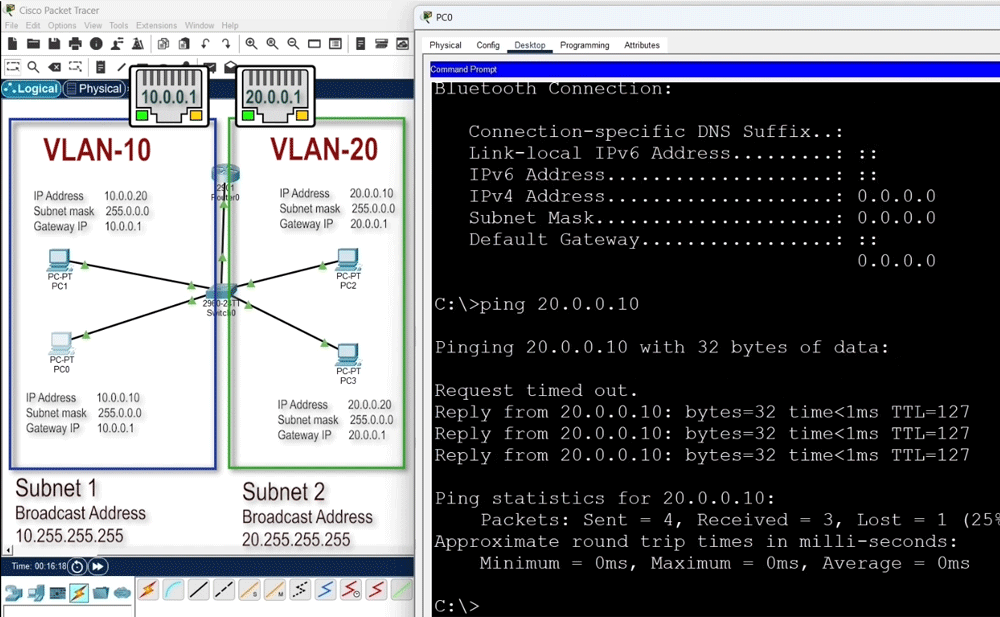
That’s all the configuration you need on the router to enable communication between both VLANs. To verify inter-VLAN communication, you can check connectivity between VLANs. Open the command prompt of a PC in the first VLAN and send ping requests to a PC in the second VLAN. Reply messages confirm the connectivity.
Now this lab is ready. The following link provides this lab with the above configuration.
Lab with the VLAN configuration
At this stage, all PCs are configured with the static IP configuration. Configure them as DHCP clients without disrupting any other existing configurations or settings.
DHCP service configurations
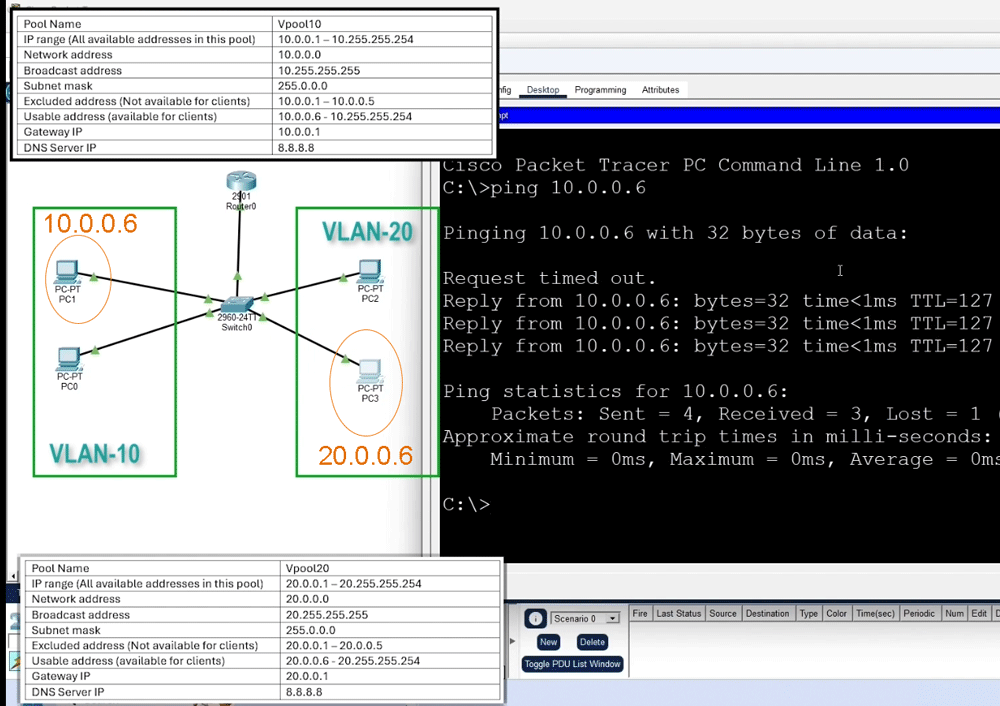
A DHCP service allocates addresses using pools. A pool defines a specific range of IP addresses available to clients. You can configure as many pools as your network requires. This lab network requires two pools, one per IP subnet. The first step in the pool configuration is to manually exclude the IP addresses you want to manage from the range. DHCP will not offer these excluded addresses to clients. You can assign them manually or reserve them for future use. After excluding the reserved IP addresses, create the pools you want. The ip dhcp pool command creates a pool and enters pool configuration mode. It needs the pool name as an argument. You can choose any descriptive name here. In pool configuration mode, define the IP address range, the default gateway IP address, and the DNS server IP address. The network command configures the IP address range. DHCP assigns an IP address from this range. The default-router command configures the gateway IP address. The dns-server command sets the DNS server IP address. That’s all the settings you need in pool configuration mode. After creating the first pool, repeat these steps for the second VLAN using addresses from the second IP subnet. Define the range, configure the gateway, set the DNS server, and exit pool configuration mode. After creating pools, you need to notify the switch which pool belongs to which VLAN. You can do this by assigning an IP address from the configured range to the VLAN. Use an excluded IP for this purpose. Enter interface VLAN configuration mode and use the IP address command to assign the IP address. Assign an excluded IP from each pool to its respective VLAN.
Switch(config)#ip dhcp excluded-address 10.0.0.1 10.0.0.5
Switch(config)#ip dhcp pool vPool10
Switch(dhcp-config)#network 10.0.0.0 255.0.0.0
Switch(dhcp-config)#default-router 10.0.0.1
Switch(dhcp-config)#dns-server 8.8.8.8
Switch(dhcp-config)#exit
Switch(config)#ip dhcp excluded-address 20.0.0.1 20.0.0.5
Switch(config)#ip dhcp pool vPool20
Switch(dhcp-config)#network 20.0.0.0 255.0.0.0
Switch(dhcp-config)#default-router 20.0.0.1
Switch(dhcp-config)#dns-server 8.8.8.8
Switch(dhcp-config)#exit
Switch(config)#interface vlan 10
Switch(config-if)#ip address 10.0.0.4 255.0.0.0
Switch(config-if)#exit
Switch(config)#interface vlan 20
Switch(config-if)#ip address 20.0.0.4 255.0.0.0
Switch(config-if)#exit
Switch(config)#

| Command | Description |
| Switch(config)#ip dhcp excluded-address 10.0.0.1 10.0.0.5 | Define the IP addresses (10.0.0.1 - 10.0.0.5) you do not want the DHCP server to assign to DHCP clients. |
| Switch(config)#ip dhcp pool vPool10 | Create a pool (vPool10) and enter pool configuration mode. |
| Switch(dhcp-config)#network 10.0.0.0 255.0.0.0 | Define the range of IP addresses you want to assign to DHCP clients. |
| Switch(dhcp-config)#default-router 10.0.0.1 | Set the gateway IP address (10.0.0.1). |
| Switch(dhcp-config)#dns-server 8.8.8.8 | Set the DNS IP address (8.8.8.8). |
| Switch(dhcp-config)#exit | Exit pool configuration mode. |
| Switch(config)#ip dhcp excluded-address 20.0.0.1 20.0.0.5 | Define the IP addresses (20.0.0.1 - 20.0.0.5) you do not want the DHCP server to assign to DHCP clients. |
| Switch(config)#ip dhcp pool vPool20 | Create a pool (vPool20) and enter pool configuration mode. |
| Switch(dhcp-config)#network 20.0.0.0 255.0.0.0 | Define the range of IP addresses you want to assign to DHCP clients. |
| Switch(dhcp-config)#default-router 20.0.0.1 | Set the gateway IP address (20.0.0.1). |
| Switch(dhcp-config)#dns-server 8.8.8.8 | Set the DNS IP address (8.8.8.8). |
| Switch(dhcp-config)#exit | Exit pool configuration mode. |
| Switch(config)#interface vlan 10 | Enter Interface configuration mode for VLAN 10 |
| Switch(config-if)#ip address 10.0.0.4 255.0.0.0 | Assign the IP address 10.0.0.4 to VLAN 10 |
| Switch(config-if)#exit | Exit Interface configuration mode |
| Switch(config)#interface vlan 20 | Enter Interface configuration mode for VLAN 20 |
| Switch(config-if)#ip address 20.0.0.4 255.0.0.0 | Assign the IP address 20.0.0.4 to VLAN 10 |
| Switch(config-if)#exit | Exit Interface configuration mode |
That’s all the configuration you need on the switch.
Verifying the DHCP service
To verify the DHCP service, open the IP configuration setting and change the option to DHCP from Static on all PCs. PCs will receive IP addresses from their corresponding IP subnet. PC0 and PC1 belong to VLAN 10. They will receive IP addresses from the subnet 10. PC2 and PC3 are in VLAN 20. They will receive IP addresses from the subnet 20. If any future changes to the IP configuration occur, you only need to update it in the pool configuration. Clients will automatically update their IP addresses according to the IP configuration received from the DHCP server. This change makes IP configuration and management completely dynamic.

To verify the existing setup, test connectivity between VLANs. Open a PC's command prompt and send ping requests to a PC on another VLAN. Reply messages confirm that this change did not affect or disrupt any existing functionality.
To view allocated IP addresses and other statistics, you can use the show commands in Privileged Exec mode on the switch. The show ip dhcp binding command lists all allocated IP addresses. These are the allocated IP addresses.
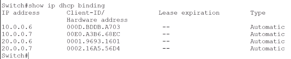
The show ip dhcp pool command accepts a pool name as an argument and displays the statistics for that pool. You can use this command to know the total number of IP addresses in the pool, the number of allocated addresses, and other statistics.

The following link provides this lab with the above configuration.
Lab with the DHCP configuration
Summary
The DHCP service dynamically provides and manages IP configurations on DHCP clients. You can configure and run it on any supported device. This tutorial explained the commands and configurations you need to set up, test, and verify this service on a Cisco switch. Understanding these steps lets you manage this service more effectively.
Author Laxmi Goswami Updated on 2026-02-16