PAT Configuration on Cisco Routers Explained
PAT (Port Address Translation) allows you to share a single IP address among multiple devices. Each device needs a unique IP address to communicate with other devices on a network. If a network has sufficient IP addresses for all of its devices, it can assign a separate IP address to each device. If it lacks available IP addresses, it can use PAT. PAT allows it to share available IP addresses. This tutorial explains how to configure, test, and verify PAT on routers with an example.
Lab setup
Build a practice lab as shown in the following image. You can use real devices or network simulator software. This tutorial uses Packet Tracer. It also provides download links to the lab used in this tutorial, with various stages.
Download PAT Practice LAB with initial IP configurations

This lab is optional. It allows you to gain hands-on experience with this topic. If you need only commands and configuration steps for PAT, you can skip it.
Initial IP configurations
| Device / Interface | IP Address | Connected With |
| Laotop0 | 10.0.0.10/8 | Fa0/0 of R0 |
| Laptop1 | 10.0.0.20/8 | Fa0/0 of R0 |
| Laptop2 | 10.0.0.30/8 | Fa0/0 of R0 |
| Server0 | 192.168.1.10/24 | Fa0/0 of R1 |
| Serial 0/0/0 of R1 | 100.0.0.1/8 | Serial 0/0/0 of R2 |
| Serial 0/0/0 of R2 | 100.0.0.2/8 | Serial 0/0/0 of R2 |
The lab provided by the download link above includes this IP configuration. Configure these IP addresses only if you build your own lab.
Assigning IP addresses to end devices
Click the end device, click Desktop, click IP configuration, select Static, and set the IP address as listed in the above table.

The following image shows this process on Server0.

Assigning IP addresses on router interfaces
Access the router's CLI prompt and run the following commands to set the IP address and hostname.

R1
Router>enable
Router# configure terminal
Router(config)#
Router(config)#hostname R1
R1(config)#interface FastEthernet0/0
R1(config-if)#ip address 10.0.0.1 255.0.0.0
R1(config-if)#no shutdown
R1(config-if)#exit
R1(config)#interface Serial0/0/0
R1(config-if)#ip address 100.0.0.1 255.0.0.0
R1(config-if)#clock rate 64000
R1(config-if)#bandwidth 64
R1(config-if)#no shutdown
R1(config-if)#exit
R1(config)#
R2
Router>enable
Router#configure terminal
Router(config)#hostname R2
R2(config)#interface FastEthernet0/0
R2(config-if)#ip address 192.168.1.1 255.255.255.0
R2(config-if)#no shutdown
R2(config-if)#exit
R2(config)#interface Serial0/0/0
R2(config-if)#ip address 100.0.0.2 255.0.0.0
R2(config-if)#no shutdown
R2(config-if)#exit
R2(config)#
Configure PAT (NAT Overload)
PAT configuration requires four steps:-
- Creating an access list of IP addresses that need translation
- Creating a pool of all IP addresses that are available for translation
- Mapping the access list with the pool
- Defining inside and outside interfaces
Creating an access list of IP addresses that need translation
Create a standard access list that defines which inside local addresses are permitted to map to inside global addresses. The following command creates a standard ACL.
Router(config)# access-list ACL_Identifier_number permit/deny matching-parameters
access-list
The command creates an ACL.
ACL_Identifier_number
This parameter defines the ACL type. There are two types of ACL: standard and extended. Both have their unique identifier numbers. Standard ACL uses two number ranges: 1-99 and 1300-1999. You can use any number within this range to indicate that you are creating a standard ACL. This number is used to group conditions under a single ACL. This number is a unique identifier for this ACL on the router.
permit/deny
An ACL condition has two actions: permit and deny. If you use the permit keyword, ACL will allow all packets from the source address specified by the next parameter. If you use the deny keyword, ACL will drop all packets from the source address specified by the next parameter.
matching-parameters
This parameter allows you to specify the contents of the packet you want to match. In a standard ACL condition, it could be a single source address or a range of addresses. You have three options to specify the source address.
- Any
- host
- A.B.C.D
Any
The Any keyword matches all sources. Every packet compared against this condition is matched.
Host
The Host keyword matches a specific host. Specify the host’s IP address next to it as an argument.
A.B.C.D
This option matches a single address or a range of addresses. To match a single address, specify its address. To match a range of addresses, use the wildcard mask.
Wildcard mask
A wildcard mask draws a boundary in the IP address. A subnet mask separates the network address from the host address. A wildcard mask distinguishes the matching portion from the rest. A wildcard mask is the inverse of the Subnet mask.
Create a standard access list that allows two hosts and denies one.
R1(config)#access-list 1 permit 10.0.0.10 0.0.0.0
R1(config)#access-list 1 permit 10.0.0.20 0.0.0.0
R1(config)#access-list 1 deny any
Creating a pool of all IP addresses that are available for translation
Define a pool of inside global addresses available for translation. Use the following command to define the NAT pool.
Router(config)#ip nat pool [Pool Name] [Start IP address] [End IP address] netmask [Subnet mask]
Pool Name: - This is the name of the pool. You can choose any descriptive name here.
Start IP Address: - The first IP address from the IP range that is available for translation.
End IP Address: - The last IP address in the available IP range. There is no minimum or maximum criteria for the IP range. For example, you can specify a single IP address or the entire range of IP addresses in a subnet.
Subnet Mask: - Subnet mask of IP range.
Create a pool named ccna with a single IP address.
R1(config)#ip nat pool ccna 50.0.0.1 50.0.0.1 netmask 255.0.0.0
Mapping the access list with the pool
The following command maps the access list to the pool.
Router(config)#ip nat inside source list [access list name or number] pool [pool name]overload
Access list name or number: - Name or number the access list you created in the first step.
Pool Name: - Name of the pool you created in the second step.
R1(config)#ip nat inside source list 1 pool ccna overload
Defining inside and outside interfaces
Define which interface is connected to the local network and which interface is connected to the global network. The following command defines an inside local.
Router(config-if)#ip nat inside
The following command defines an inside global.
Router(config-if)#ip nat outside

PAT (NAT Overload) configuration on R1
R1>enable
R1#configure terminal
R1(config)#access-list 1 permit 10.0.0.10 0.0.0.0
R1(config)#access-list 1 permit 10.0.0.20 0.0.0.0
R1(config)#access-list 1 deny any
R1(config)#ip nat pool ccna 50.0.0.1 50.0.0.1 netmask 255.0.0.0
R1(config)#ip nat inside source list 1 pool ccna overload
R1(config)#interface FastEthernet 0/0
R1(config-if)#ip nat inside
R1(config-if)#exit
R1(config)#interface Serial 0/0/0
R1(config-if)#ip nat outside
R1(config-if)#exit
R1(config)#
The above configuration adds only two addresses for translation while keeping one address for testing. Since the second router has only one address, you can configure Static NAT to keep the configuration straightforward.
R2>enable
R2#configure terminal
R2(config)#ip nat inside source static 192.168.1.10 200.0.0.10
R2(config)#interface Serial 0/0/0
R2(config-if)#ip nat outside
R2(config-if)#exit
R2(config)#interface FastEthernet 0/0
R2(config-if)#ip nat inside
R2(config-if)#exit
R2(config)#
This tutorial is part of the tutorial series "NAT (Network Address Translation) Concepts, Configurations, and Terminology Explained". Other parts of this series are the following.
Chapter 1 Basic Concepts of NAT Explained in Easy Language
Chapter 2 How to Configure Static NAT on Cisco Routers
Chapter 3 How to Configure Dynamic NAT on Cisco Routers
Chapter 4 Configure PAT on Cisco Routers with Examples
Enable routing
Networks on different routers can communicate only if routing is enabled on each router. The following command enables routing on the first router (R1).
R1(config)#ip route 200.0.0.0 255.255.255.0 100.0.0.2
The following command enables routing on the second router.
R2(config)#ip route 50.0.0.0 255.0.0.0 100.0.0.1
Testing PAT Configuration
This lab has PAT configuration on R1 and Static NAT configuration on R2. To test this setup, click Laptop0 and Desktop and click Command Prompt.
- Run the ipconfig command.
- Run the ping 200.0.0.10 command.
- Run the ping 192.168.1.10 command.

The first command displays the host system's IP configuration.
The second command checks connectivity with the translated IP address. If the remote device is reachable at the translated IP address, it will respond to ping messages.
The third command confirms that the remote device is unreachable at its original IP address.
You can also verify the same by accessing the web service running on the remote server.
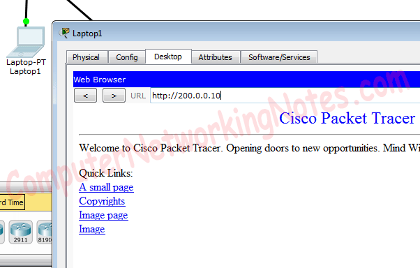
Run the ping 200.0.0.10 command on Laptop2.

Access the web service from the same host.

Since you configured PAT only for two hosts (Laptop0 [10.0.0.10] and Laptop1 [10.0.0.20]), the third host (Laptop2 [10.0.0.3]) cannot use PAT.
The following link provides the lab used in this tutorial with all configurations.
Download link: Practice LAB with PAT configuration
Viewing PAT translation on routers
Use the show ip nat translation command on routers to view PAT translation.

The above output verifies that the same inside global IP address is used to translate all the inside local IP addresses. For each inside local IP address, a unique port number is used.
The following image shows the output of this command on R2.

In the output above, the Outside global field confirms that all packets are originating from a single IP address.
Conclusion
Configuring PAT on Cisco routers allows multiple devices to share a single public IP address, making efficient use of limited IP resources. By following the steps outlined in this tutorial, you can successfully implement and troubleshoot PAT. Understanding these concepts is essential for effective network management, especially where public IP addresses are limited. With hands-on practice, you can apply PAT configurations confidently in real-world scenarios.
Author Laxmi Goswami Updated on 2026-04-10