Hot Standby Router Protocol Explained
A default gateway router connects a network's local subnet to a remote subnet of the same network or another network. By default, you can configure only one default gateway router. If the configured default gateway fails, the connected network loses its connectivity. HSRP (Hot Standby Router Protocol) allows you to configure multiple default gateways. This tutorial explains the basic concepts and configuration steps of HSRP through an example on Packet Tracer.
What is HSRP?
FHRP (First Hop Redundancy Protocol) protocols provide a default gateway router redundancy. HSRP is a member of the FHRP protocols. It is a Cisco proprietary protocol. It operates exclusively on Cisco routers. It allows one router to automatically take over if another fails. In other words, it provides gateway-router redundancy by automatically replacing a failed gateway router with a functional one.
Basic concepts of HSRP
HSRP is based on an active/passive (standby) model. The following steps outline this concept.
- Form a group of all available devices.
- Select a device as the main device.
- Keep only the main device active.
- Put all other devices in the passive state or standby state.
- If the main device fails, select a passive device from the available passive devices and make it an active device by changing its state to active.
HSRP Terminology
HSRP terminology involves the terms HSRP uses to describe its features and functions.
HSRP group / Standby group
An HSRP group consists of all gateway routers connected to the local subnet that are configured to provide default gateway services. Routers not included in this group cannot serve as the default gateway.
Virtual IP address
A virtual IP address is the group address of the HSRP group. This address is assigned to all member routers of the HSRP group. The virtual IP address belongs to the same IP subnet used to connect the local subnet to the gateway router's physical interface.
The same virtual IP address is configured on all member routers. Each member router needs this IP address along with its physical IP address. In other words, each member router has two IP addresses: the physical IP address and the virtual IP address.
The physical IP address is the IP address of the interface that is connected to the local subnet. Each physical interface uses a unique IP address. A virtual IP address is an additional IP address of the interface that is connected to the local subnet. All physical interfaces of the HSRP group use the same virtual IP address.
Virtual MAC address
A MAC address is the physical address of an interface, required for communication between interfaces. To communicate with the default gateway, interfaces on the local subnet require the MAC address of the default gateway interface. When a virtual IP address is configured on the member interfaces of an HSRP group, HSRP automatically generates a virtual MAC address and associates it with the virtual IP address.
Virtual Router
A virtual router connects the local subnet to the main gateway router. Hosts on the local subnet forward data packets to the virtual router, which then forwards them to their destination. The virtual router is not a physical device. It is a role played by one member router of the HSRP group. Technically, the virtual router is the currently active default router.
The following image shows the role of the virtual router in HSRP implementation.

Active router
An active router is the main router. An active router is a physical router that serves as a virtual router. It receives traffic from the local subnet and forwards it to the destination.
Standby router
A standby router is the backup router of the main router. If the main router fails, the standby router quickly takes over the responsibilities of the main router. In other words, if the primary router fails, HSRP automatically transfers the virtual router's role to the standby router.
Other routers
The other router is a backup router of the standby router. You can add up to 255 routers in an HSRP group. If the main router fails, the standby router takes over the responsibilities of the main router, and the other router takes over the responsibilities of the standby router. In simple words, if an HSRP group router is not an active or standby router, then it is the other router.
The following image shows the role of the virtual router, active router, standby router, and other routers.
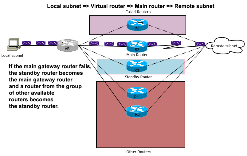
HSRP Example
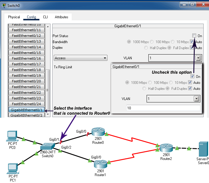
Create a practice lab as shown in the following image. You can use any network simulator software or real devices for this lab. Commands and configuration steps are the same on all platforms. This tutorial uses Packet Tracer. It also provides the lab created and configured in this exercise.
Download link: HSRP practice LAB with initial configuration
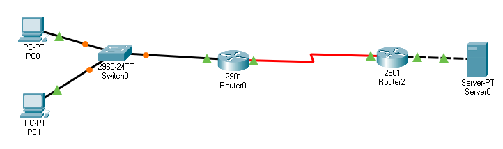
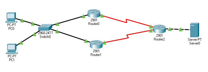
This lab has three components: a local network, a WAN link, and a remote network. The local network is connected to the remote network through the WAN link. The local network has only one path to reach the remote network, and that path goes through Router0. Router0 is the default gateway of the local network. If it fails, the local network cannot access the remote network. To prevent this single point of failure, a backup router is added as shown in the following image.
Initial IP configuration
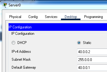
Configure Router0, Router1, Router2, and Server0 as shown in the following image.
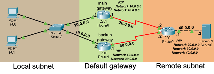
The lab provided by the above download link includes this initial IP configuration.
Router0 (main gateway router) configuration
Router>enable
Router#configure terminal
Router(config)#interface GigabitEthernet0/0
Router(config-if)#ip address 10.0.0.1 255.0.0.0
Router(config-if)#no shutdown
Router(config-if)#
Router(config-if)#exit
Router(config)#interface Serial0/0/1
Router(config-if)#ip address 20.0.0.1 255.0.0.0
Router(config-if)#no shutdown
Router(config-if)#exit
Router(config)#router rip
Router(config-router)#network 10.0.0.0
Router(config-router)#network 20.0.0.0
Router(config-router)# exit
Router(config)#
Router1 (backup gateway router) configuration
Router>enable
Router#configure terminal
Router(config)#interface GigabitEthernet0/0
Router(config-if)#ip address 10.0.0.2 255.0.0.0
Router(config-if)#no shutdown
Router(config-if)#exit
Router(config)#interface Serial0/0/0
Router(config-if)#ip address 30.0.0.1 255.0.0.0
Router(config-if)#no shutdown
Router(config-if)#exit
Router(config)#router rip
Router(config-router)#network 10.0.0.0
Router(config-router)#network 30.0.0.0
Router(config-router)#
Router2 configuration
Router>enable
Router#configure terminal
Router(config)#interface GigabitEthernet0/0
Router(config-if)#ip address 40.0.0.1 255.0.0.0
Router(config-if)#no shutdown
Router(config-if)#exit
Router(config)#interface Serial0/0/0
Router(config-if)#ip address 30.0.0.2 255.0.0.0
Router(config-if)#no shutdown
Router(config-if)#exit
Router(config)#interface Serial0/0/1
Router(config-if)# ip address 20.0.0.2 255.0.0.0
Router(config-if)#no shutdown
Router(config-if)#exit
Router(config)#router rip
Router(config-router)# network 20.0.0.0
Router(config-router)#network 30.0.0.0
Router(config-router)#network 40.0.0.0
Router(config-router)# exit
Router(config)#
IP configuration Server
HSRP configuration
HSRP configuration is straightforward. It requires only one command. Run the following command in sub-configuration mode of the interface that provides the default gateway functionality.
Router(config-if)#standby [group-id] ip [ip-address]
The group-id is the group number of HSRP.
The ip-address is a virtual IP address you want to use as the default gateway’s IP address.
You need to run the same command on all interfaces (main and backup) that you want to use as the default gateway for the local subnet. In this example network, Router0's GigabitEthernet0/0 is the main gateway interface. Router1's GigabitEthernet0/0 serves as the backup gateway interface.
Run the following command on both interfaces.
Router(config-if)#standby 1 ip 10.0.0.10
This command sets the HSRP group number to 1 and assigns 10.0.0.10 as the virtual default gateway IP address. You can use any number as the group number within the range 0 to 4095. However, after selecting a group number, you must use the same number on all interfaces.
The virtual IP address must belong to the IP subnet of the main physical gateway interface. In this example, the main gateway interface uses the 10.0.0.0/24 subnet. Same as the group number, the same virtual IP address must be configured on all interfaces participating in HSRP.
HSRP configuration of Router0 (main gateway router)
Router>enable
Router#configure terminal
Router(config)#interface gigabitEthernet 0/0
Router(config-if)#standby 1 ip 10.0.0.10
Router(config-if)#exit
Router(config)#
HSRP configuration of Router1 (backup gateway router)
Router>enable
Router#configure terminal
Router(config)#interface gigabitEthernet 0/0
Router(config-if)#standby 1 ip 10.0.0.10
Router(config-if)#exit
Router(config)#
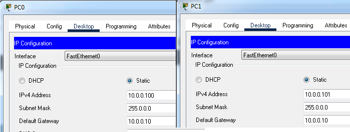
Default gateway configuration on end devices
Without HSRP, you configure the IP address of the router’s interface connected to the local network as the default gateway IP address. With HSRP, you configure end devices to use the virtual gateway IP address rather than the physical gateway IP address. Assign an IP configuration to both PCs.
Verifying HSRP configuration
To verify the HSRP configuration, first test connectivity between the local and remote subnets, and note the path the hosts on the local subnet use to access the remote subnet. To test connectivity, you can use the ping command. To print the path, you can use the tracert command. The following image shows the output of both commands.
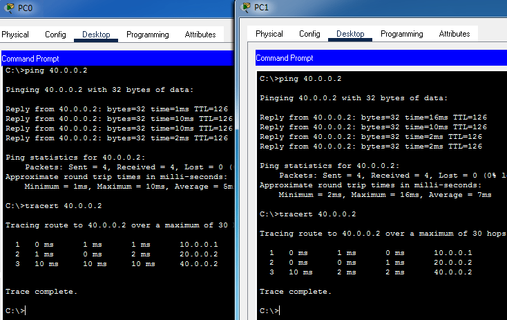
The above output confirms that the local subnet is connected to the remote host through the default gateway. To simulate a main gateway router failure, either remove the link connecting Router0 to Switch or disable the switch interface connected to Router0.
Retest the connectivity between the local and the remote subnets.

If HSRP is configured, it automatically replaces the failed gateway router with an available standby router. As shown in the output above, the local subnet remains connected to the remote network via a different (backup) path, confirming that the failed gateway has been replaced.
The following download link provides this lab with HSRP configuration. It contains all the configurations explained in this tutorial.
Download link: Practice lab with HSRP configuration
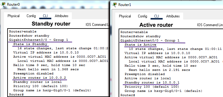
The show standby command
The show standby command displays the router's current state, the HRSP group number, and the virtual IP address.
Conclusion
This tutorial presented a basic HSRP configuration. This configuration is straightforward and allows you to implement HSRP in your network with ease. It automatically selects the main and backup routers based on their startup order. It chooses the router that powers up first as the main router and the router that powers up later as the backup router.
Author Laxmi Goswami Updated on 2026-04-13