HSRP Configuration and Load Balancing Explained
HSRP (Hot Standby Router Protocol) is a Cisco proprietary protocol. It dynamically manages multiple default gateway routers. It creates a group and adds all available gateway routers to that group. Afterward, it selects two routers: one as the main (or active) router and the other as the standby (or passive) router. The main router forwards the traffic. The standby router waits for the main router to fail. If the main router fails, the standby router takes over the responsibilities of the main router. If the standby router fails, one of the remaining routers takes over its responsibilities.
The major drawback of this concept is that it does not utilize all routers effectively. At a time, it uses only one router and keeps all remaining routers in the standby position. For example, if you have ten gateway routers, at any given time, it will use only one router and keep the remaining nine in the waiting or standby position.
To overcome this limitation, you can design your network to support multiple instances of HSRP. By running multiple instances of HSRP, you can use all routers simultaneously. This process is known as HSRP load balancing.
Lab setup for HSRP practice
Set up a practice lab as shown in the following image. You can use any network simulator software or real devices for this. This tutorial uses Packet Tracer. It also provides download links for the lab created and used in this tutorial.

In this example network, the local subnet contains end-user systems, and the remote subnet contains a Server. The local subnet is connected to the remote subnet via WAN links. For redundancy, three gateway routers (R1, R2, and R3) are used to connect the local subnet to the remote subnet.
When dynamically managing gateway routers, if you configure HSRP, only one router will be used at a time. To use all routers simultaneously, you need to configure multiple HSRP instances. To configure multiple instances of HSRP, divide the network into sub-networks. After dividing the network into subnetworks, configure a separate HSRP instance on each subnetwork.
This example network contains three gateway routers. To use three gateway routers simultaneously, configure three instances of HSRP. To configure three instances of HSRP, divide the network into three sub-networks. To divide the network, you can use VLANs. VLANs divide a network into sub-networks.
VLANs are logical. To implement VLANs in the network, you don't need to modify the physical layout of the network. A VLAN creates a logical boundary. Devices within the VLAN boundary can't access devices outside the boundary. In simple words, devices inside a VLAN and devices outside the VLAN belong to two separate networks and can't communicate without a router. In this example, you can divide the local subnet into three VLANs and configure a separate instance of HSRP in each VLAN.
To learn how VLANs work and how to configure VLANs in a network, you can use the following article.
Initial configuration
The initial configuration allows you to verify, test, and debug the HSRP configuration. The initial configuration includes the following settings.
- IP configuration on all interfaces
- The same routing protocol on all routers
- The same VLANs database on all switches
- VLAN configuration on all interfaces that are connected to the local subnet
- DTP configuration on all interfaces that carry data of multiple VLANs
- Router-on-stick configuration on the interface that provides connectivity between multiple VLANs
The following image shows the initial configuration for this lab network.

The following link provides this lab with the initial configurations.
HSRP Packet Tracer lab with the initial configurations
Configuring the initial configuration
This section describes how to configure the initial setup for this lab network. If you are using the pre-configured lab, skip this section. The pre-configured lab already contains this initial configuration.
R1
R1>enable
R1#configure terminal
R1(config)#interface Serial0/0/0
R1(config-if)#ip address 40.0.0.1 255.0.0.0
R1(config-if)#no shutdown
R1(config-if)#exit
R1(config)#interface gigabitEthernet 0/0
R1(config-if)#no ip address
R1(config-if)#no shutdown
R1(config-if)#exit
R1(config)#interface gigabitEthernet 0/0.10
R1(config-subif)#encapsulation dot1Q 10
R1(config-subif)#ip address 10.0.0.1 255.0.0.0
R1(config-subif)#exit
R1(config)#interface gigabitEthernet 0/0.20
R1(config-subif)#encapsulation dot1Q 20
R1(config-subif)#ip address 20.0.0.1 255.0.0.0
R1(config-subif)#exit
R1(config)#interface gigabitEthernet 0/0.30
R1(config-subif)#encapsulation dot1Q 30
R1(config-subif)#ip address 30.0.0.1 255.0.0.0
R1(config-subif)#exit
R1(config)#router rip
R1(config-router)#network 10.0.0.0
R1(config-router)#network 20.0.0.0
R1(config-router)#network 30.0.0.0
R1(config-router)#network 40.0.0.0
R1(config-router)# exit
R1(config)#
R2
R2>enable
R2#configure terminal
R2(config)#interface Serial0/0/0
R2(config-if)#ip address 50.0.0.1 255.0.0.0
R2(config-if)#no shutdown
R2(config-if)#exit
R2(config)#interface gigabitEthernet 0/0
R2(config-if)#no ip address
R2(config-if)#no shutdown
R2(config-if)#exit
R2(config)#interface gigabitEthernet 0/0.10
R2(config-subif)#encapsulation dot1Q 10
R2(config-subif)#ip address 10.0.0.2 255.0.0.0
R2(config-subif)#exit
R2(config)#interface gigabitEthernet 0/0.20
R2(config-subif)#encapsulation dot1Q 20
R2(config-subif)#ip address 20.0.0.2 255.0.0.0
R2(config-subif)#exit
R2(config)#interface gigabitEthernet 0/0.30
R2(config-subif)#encapsulation dot1Q 30
R2(config-subif)#ip address 30.0.0.2 255.0.0.0
R2(config-subif)#exit
R2(config)#router rip
R2(config-router)#network 10.0.0.0
R2(config-router)#network 20.0.0.0
R2(config-router)#network 30.0.0.0
R2(config-router)#network 50.0.0.0
R2(config-router)# exit
R3
R3>enable
R3#configure terminal
R3(config)#interface Serial0/0/0
R3(config-if)#ip address 60.0.0.1 255.0.0.0
R3(config-if)#no shutdown
R3(config-if)#exit
R3(config)#interface gigabitEthernet 0/0
R3(config-if)#no ip address
R3(config-if)#no shutdown
R3(config-if)#exit
R3(config)#interface gigabitEthernet 0/0.10
R3(config-subif)#encapsulation dot1Q 10
R3(config-subif)#ip address 10.0.0.3 255.0.0.0
R3(config-subif)#exit
R3(config)#interface gigabitEthernet 0/0.20
R3(config-subif)#encapsulation dot1Q 20
R3(config-subif)#ip address 20.0.0.3 255.0.0.0
R3(config-subif)#exit
R3(config)#interface gigabitEthernet 0/0.30
R3(config-subif)#encapsulation dot1Q 30
R3(config-subif)#ip address 30.0.0.3 255.0.0.0
R3(config-subif)#exit
R3(config)#router rip
R3(config-router)#network 10.0.0.0
R3(config-router)#network 20.0.0.0
R3(config-router)#network 30.0.0.0
R3(config-router)#network 60.0.0.0
R3(config-router)# exit
R3(config)#
RemoteRouter(RR)
Router>enable
Router#configure terminal
Router(config)#interface Serial0/0/0
Router(config-if)#ip address 40.0.0.2 255.0.0.0
Router(config-if)#no shutdown
Router(config-if)#exit
Router(config)#interface Serial0/0/1
Router(config-if)#ip address 50.0.0.2 255.0.0.0
Router(config-if)#no shutdown
Router(config-if)#exit
Router(config)#interface Serial0/1/0
Router(config-if)#ip address 60.0.0.2 255.0.0.0
Router(config-if)#no shutdown
Router(config-if)#exit
Router(config)#interface GigabitEthernet0/0
Router(config-if)#ip address 70.0.0.1 255.0.0.0
Router(config-if)#no shutdown
Router(config-if)#
Router(config-if)#exit
Router(config)#router rip
Router(config-router)#network 70.0.0.0
Router(config-router)#network 60.0.0.0
Router(config-router)#network 50.0.0.0
Router(config-router)#network 40.0.0.0
Router(config-router)# exit
Router(config)#
VLAN and DTP configuration
Switch1
Use the following commands to configure VLANs on the local subnet.
S1>enable
S1#configure terminal
S1(config)#vlan 10
S1(config-vlan)#exit
S1(config)#vlan 20
S1(config-vlan)#exit
S1(config)#vlan 30
S1(config-vlan)#exit
S1(config)#interface fastEthernet 0/1
S1(config-if)#switchport access vlan 10
S1(config-if)#exit
S1(config)#interface fastEthernet 0/2
S1(config-if)#switchport access vlan 20
S1(config-if)#exit
S1(config)#interface fastEthernet 0/3
S1(config-if)#switchport access vlan 30
S1(config-if)#exit
S1(config)#interface gigabitEthernet 0/1
S1(config-if)#switchport mode trunk
S1(config-if)#exit
S1(config)#interface fastEthernet 0/24
S1(config-if)#switchport mode trunk
S1(config-if)#exit
S1(config)#interface fastEthernet 0/23
S1(config-if)#switchport mode trunk
S1(config-if)#exit
S1(config)#
Switch2
S2>enable
S2#configure terminal
S2(config)#vlan 10
S2(config-vlan)#exit
S2(config)#vlan 20
S2(config-vlan)#exit
S2(config)#vlan 30
S2(config-vlan)#exit
S2(config)#interface fastethernet 0/1
S2(config-if)#switchport access vlan 10
S2(config-if)#exit
S2(config)#interface fastethernet 0/2
S2(config-if)#switchport access vlan 20
S2(config-if)#exit
S2(config)#interface fastethernet 0/3
S2(config-if)#switchport access vlan 30
S2(config-vlan)#exit
S2(config)#interface gigabitEthernet 0/1
S2(config-if)#switchport mode trunk
S2(config-if)#exit
S2(config)#interface fastEthernet 0/24
S2(config-if)#switchport mode trunk
S2(config-if)#exit
S2(config)#interface fastEthernet 0/23
S2(config-if)#switchport mode trunk
S2(config-if)#exit
S2(config)#interface fastEthernet 0/22
S2(config-if)#switchport mode trunk
S2(config-if)#exit
S2(config)#interface fastEthernet 0/21
S2(config-if)#switchport mode trunk
S2(config-if)#exit
S2(config)#
Switch3
S3>enable
S3#configure terminal
S3(config)#vlan 10
S3(config-vlan)#exit
S3(config)#vlan 20
S3(config-vlan)#exit
S3(config)#vlan 30
S3(config-vlan)#exit
S3(config)#interface fastEthernet 0/1
S3(config-if)#switchport access vlan 10
S3(config-if)#exit
S3(config)#interface fastEthernet 0/2
S3(config-if)#switchport access vlan 20
S3(config-if)#exit
S3(config)#interface fastEthernet 0/3
S3(config-if)#switchport access vlan 30
S3(config-if)#exit
S3(config)#interface gigabitEthernet 0/1
S3(config-if)#switchport mode trunk
S3(config-if)#exit
S3(config)#interface fastEthernet 0/21
S3(config-if)#switchport mode trunk
S3(config-if)#exit
S3(config)#interface fastEthernet 0/22
S3(config-if)#switchport mode trunk
S3(config-if)#exit
S3(config)#
The IP configuration on Server0
Implementing the HSRP protocol
The following command configures HSRP.
Router(config-subif)#standby HSRP_Group_Number ip Virtual_IP_Address
In this command:-
The HSRP_Group_Number is the HSRP group number.
The Virtual_IP_address is the virtual IP address of the HSRP group.
You need to run this command on all interfaces you want to use as the default gateway for a particular subnetwork (or VLAN).
This example network divides the local network into the three VLANs (sub-networks): VLAN10, VLAN20, and VLAN30. The following table lists the group ID (HSRP group number) and group IP (HSRP virtual IP) for these VLANs.
| VLAN | Router | Interface | Interface IP | HSRP Group | HSRP IP |
| 10 | R1 | G0/0.10 | 10.0.0.1 | 10 | 10.0.0.10 |
| 10 | R2 | G0/0.10 | 10.0.0.2 | 10 | 10.0.0.10 |
| 10 | R3 | G0/0.10 | 10.0.0.3 | 10 | 10.0.0.10 |
| 20 | R1 | G0/0.20 | 20.0.0.1 | 20 | 20.0.0.10 |
| 20 | R2 | G0/0.20 | 20.0.0.2 | 20 | 20.0.0.10 |
| 20 | R3 | G0/0.20 | 20.0.0.3 | 20 | 20.0.0.10 |
| 30 | R1 | G0/0.30 | 30.0.0.1 | 30 | 30.0.0.10 |
| 30 | R2 | G0/0.30 | 30.0.0.2 | 30 | 30.0.0.10 |
| 30 | R3 | G0/0.30 | 30.0.0.3 | 30 | 30.0.0.10 |
If you only want to implement HSRP, the above command and configuration are sufficient. You don't need any further configuration. However, with this configuration, only one router will work at a time. To use all routers simultaneously, you need to configure HSRP load balancing.
Configuring the HSRP load balancing
By default, HSRP sets a router as the main router if it comes up first. For example, if you have three routers in an HSRP group. The router that starts first will be selected as the main router. Once the main router is selected, HSRP does not run the selection process again until the main router remains available.
To configure HSRP load balancing, you must adjust the priority sequence so that if a router is active in one VLAN, it does not become active in other VLANs. You also need to configure HSRP so that it always uses your sequence, regardless of which router starts first. The following commands allow you to set priority.
#standby HSRP_Group_ID priority Priority_Sequence
#standby HSRP_Group_ID preempt
The first command sets the priority of the interface (router) in the HSRP group. You can set any value between 0 and 255. The default value is 100. If you do not use this command, HSRP assigns the default priority to the interface. HSRP selects the interface that has the highest value. For example, if two interfaces have priority values of 120 and 140, the interface with priority 140 will be selected.
The second command instructs HSRP to always use the configured sequence, regardless of which router starts first or last. Run this command only on the interface you want to make active for the VLAN.
The following table lists the priority values used in this lab network.
| VLAN | Router | Interface | Priority | Preempt |
| 10 | R1 | G0/0.10 | 120 | yes |
| 10 | R2 | G0/0.10 | 100 (default) | |
| 10 | R3 | G0/0.10 | 110 | |
| 20 | R1 | G0/0.20 | 110 | |
| 20 | R2 | G0/0.20 | 120 | yes |
| 20 | R3 | G0/0.20 | 100 (default) | |
| 30 | R1 | G0/0.30 | 100 (default) | |
| 30 | R2 | G0/0.30 | 110 | |
| 30 | R3 | G0/0.30 | 120 | yes |
R1
R1>enable
R1#configure terminal
R1(config)#interface gigabitEthernet 0/0.10
R1(config-subif)#standby 10 ip 10.0.0.10
R1(config-subif)#standby 10 priority 120
R1(config-subif)#standby 10 preempt
R1(config-subif)#exit
R1(config)#interface gigabitEthernet 0/0.20
R1(config-subif)#standby 20 ip 20.0.0.10
R1(config-subif)#standby 20 priority 110
R1(config-subif)#exit
R1(config)#interface gigabitEthernet 0/0.30
R1(config-subif)#standby 30 ip 30.0.0.10
R1(config-subif)#exit
R1(config)#
R2
R2>enable
R2#configure terminal
R2(config)#interface gigabitEthernet 0/0.10
R2(config-subif)#standby 10 ip 10.0.0.10
R2(config-subif)#exit
R2(config)#interface gigabitEthernet 0/0.20
R2(config-subif)#standby 20 ip 20.0.0.10
R2(config-subif)#standby 20 priority 120
R2(config-subif)#standby 20 preempt
R2(config-subif)#exit
R2(config)#interface gigabitEthernet 0/0.30
R2(config-subif)#standby 30 ip 30.0.0.10
R2(config-subif)#standby 30 priority 110
R2(config-subif)#exit
R2(config)#
R3
R3>enable
R3#configure terminal
R3(config)#interface gigabitEthernet 0/0.10
R3(config-subif)#standby 10 ip 10.0.0.10
R3(config-subif)#standby 10 priority 110
R3(config-subif)#exit
R3(config)#interface gigabitEthernet 0/0.20
R3(config-subif)#standby 20 ip 20.0.0.10
R3(config-subif)#exit
R3(config)#interface gigabitEthernet 0/0.30
R3(config-subif)#standby 30 ip 30.0.0.10
R3(config-subif)#standby 30 priority 120
R3(config-subif)#standby 30 preempt
R3(config-subif)#exit
R3(config)#
Configure or update the IP configuration on all PCs on the local subnet to use the virtual IP address of the HSRP group as the default gateway. The following table lists the IP configuration of all PCs.
| PC | VLAN | HSRP Group | IP Address | Subnet mask | Gateway IP |
| V10PC1 | 10 | 10 | 10.0.0.100 | 255.0.0.0 | 10.0.0.10 |
| V20PC1 | 10 | 10 | 10.0.0.101 | 255.0.0.0 | 10.0.0.10 |
| V30PC1 | 10 | 10 | 10.0.0.102 | 255.0.0.0 | 10.0.0.10 |
| V20PC1 | 20 | 20 | 20.0.0.100 | 255.0.0.0 | 20.0.0.10 |
| V20PC2 | 20 | 20 | 20.0.0.101 | 255.0.0.0 | 20.0.0.10 |
| V20PC3 | 20 | 20 | 20.0.0.102 | 255.0.0.0 | 20.0.0.10 |
| V30PC1 | 20 | 30 | 30.0.0.100 | 255.0.0.0 | 30.0.0.10 |
| V30PC2 | 20 | 30 | 30.0.0.101 | 255.0.0.0 | 30.0.0.10 |
| V30PC3 | 20 | 30 | 30.0.0.102 | 255.0.0.0 | 30.0.0.10 |
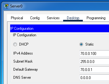
Assign IP configurations to all PCs listed in the table above. The following image shows the IP configuration on V10PC1.

Testing and verifying HSRP load balancing
To verify the HSRP configuration, you can use the "ping" and "tracert" commands. Use the ping command to test connectivity between the PC and Server0. Use the tracert command to print the path between the PC and Server0. If HSRP is properly configured, the main gateway router will forward the packet.

Power off the switch's interface that connects the PC to the default gateway router.

Wait for a few seconds, and run both commands on the PC again. If the PC can still access the Server, it verifies that the HSRP configuration is working properly. It also verifies that the failed gateway router has been replaced by the standby router.

Power on the switch's interface again, wait for a few seconds, and run both commands again. This time, the PC should take the original path again. The main gateway router should be the original gateway router again.

You can repeat this process from other PCs to do more testing.
The following link provides the lab used in this tutorial with all configurations.
HSRP Packet Tracer lab with all configurations
Debugging and troubleshooting HSRP configuration
If the HSRP configuration does not work, follow these steps to debug and troubleshoot it.
Check the IP configuration of PCs
PCs of the local subnet must be configured to forward traffic to the virtual IP address of the HSRP group. If PCs are configured to forward traffic to the router's physical interface, HSRP will not work.
Check the HSRP group ID members
The HSRP group ID must be the same on all members. HSRP uses the group ID to add an interface to the group. If two interfaces are configured with different group IDs, they will belong to different groups.
Check the virtual IP address on all members
HSRP uses the virtual IP address to receive traffic from the local subnet. If two interfaces in the same HSRP group are configured with different virtual IP addresses, the interface with the virtual IP configured as the default gateway IP on the local subnet will receive traffic from the local subnet. You can use the "show standby brief" command to view the standby configuration on the router. The following image shows the output of this command.

This command provides the summarized version of the configuration. To view the detailed configuration, use the "show standby" command.
Conclusion
Configuring HSRP and implementing load balancing on Cisco routers enhances network reliability and optimizes resource utilization. By leveraging multiple HSRP instances and VLANs, you can ensure that all available routers share the traffic load, eliminating single points of failure and maximizing uptime. Proper configuration and thorough testing are essential to verify redundancy and seamless failover.
Author Laxmi Goswami Updated on 2026-04-28