Diagnosing Interface and Cable Issues
Many possible reasons that can prevent a host from accessing resources in a wired network. The physical path the host uses to reach the network is the most common cause and should be checked first when troubleshooting. It includes two cable types: Ethernet and Fiber. Common causes of Ethernet link failures include excessive cable length, interface issues, loose connectors, poor termination, a cable break, the wrong cable type, incorrect pinouts, and pair integrity issues. For fiber optic cables, these causes include optical compatibility, polarity, incorrect cable type, connector cleanliness, a break or bend in the cable, and transceiver issues. This tutorial explains how to identify and diagnose these issues.
CCNA 2.0 Exam objectives covered in this tutorial
1.0 Network Infrastructure and Connectivity
1.1 Diagnose interface and cable (copper and fiber) issues such as collisions, errors, mismatched duplex, speed, distance, interface, signal levels, pinout, and cable types.
Copper Ethernet cables
An Ethernet cable contains eight copper wires in four pairs. It comes in two types (STP and UTP) and many variations (Cat5, Cat6, Cat7, etc.). The main difference between STP (Shielded Twisted Pair) and UTP (Unshielded Twisted Pair) is that STP adds an extra plastic layer around each pair.

RJ-45 connectors terminate both ends of Ethernet cables. An RJ-45 connector contains 8 pins to connect 8 wires of an Ethernet cable.

A NIC uses pins 1 and 2 to transmit data. To receive data, it uses pins 3 and 6. A switch does the opposite. It receives data on pins 1 and 2 and transmits data from pins 3 and 6. Based on the devices you want to connect, you can adjust the wire positions in the RJ-45 connectors at both ends in two ways: straight-through or crossover.
Ethernet straight-through cable (MDI wiring)
This cable places wires in the same position at both ends. The wire at pin one on one end of the cable connects to pin one on the other end. The wire at pin two connects to pin two on the other end, and so on. This wiring type is called MDI. The following table lists the wire positions of a straight-through cable on both sides.
| Side A | Side B |
| Green White | Green White |
| Green | Green |
| Orange White | Orange White |
| Blue | Blue |
| Blue White | Blue White |
| Orange | Orange |
| Brown White | Brown White |
| Brown | Brown |
The following image shows the straight-through cable.

The following device requires MDI wiring.
PC to Switch
PC to Hub
Router to Switch
Switch to Server
Hub to Server

Ethernet crossover (MDIX wiring)
This cable connects the transmitting pins on one side to the receiving pins on the other. The wire at pin one on one end of the cable connects to pin three on the other end. The wire at pin two connects to pin six on the other end of the cable. The remaining wires connect in the same positions at both ends. This type of wiring is called MDIX. The following table lists the wire positions for a crossover cable on both sides.
| Side A | Side B |
| Green White | Orange White |
| Green | Orange |
| Orange White | Green White |
| Blue | Blue |
| Blue White | Blue White |
| Orange | Green |
| Brown White | Brown White |
| Brown | Brown |
The following image shows the crossover cable's color coding.

The following device requires MDIX wiring.
PC to PC
Hub to hub
A hub to a switch
A cable modem to a router
Two router interfaces

Real world
Modern networking devices and interfaces support a feature called auto-MDIX. It is a hardware feature on NICs and Ethernet ports that automatically detects the correct transmit (TX) and receive (RX) pin configuration. It eliminates the need for crossover cables. It lets you use a straight-through patch cable for almost any link. Most modern switches, routers, and NICs enable it by default.
Exam bytes
A correct cable is required for connectivity. An incorrect cable will result in no link light, intermittent connectivity, or negotiation failure. The auto-MDIX feature is applicable in the real world. It does not apply in the exam. The exam may include underlying cable-selection questions or present older equipment in scenarios where the pinout remains decisive.
Diagnosing Ethernet cable issues
Common Ethernet cable issues include excessive cable length, interface issues, loose connectors, poor termination, cable breaks, the wrong cable type, incorrect pinouts, and poor pair integrity.
Cable length
Ethernet cables come in many variations, classified as Categories. Different categories may support different cable lengths, data transmission speeds, and other relevant features. However, for the CCNA exam, the standard cable length is 100 meters, including patch cabling. A longer link may fail, negotiate inconsistently, or accumulate errors even when the configuration is correct.
EMI (Electromagnetic interference)
The environment in which Ethernet cables run heavily affects their performance. If they run near heavy machinery or electrical equipment, data transmission speed may drop.
Physical damage or loose connectors
Physically damaged, tightly bent, crushed, or broken cable can also bring the link down. A visual inspection is required to find and fix this issue.
Summary
| Symptom | Possible causes | Diagnose |
| No link | The cable is unplugged. The cable is broken. A connector in the path is loose. | Physically inspect the entire path for any cable break and loose connectors. |
| Flapping Link | The cable exceeds the supported length. Incorrect pinouts in connectors. The wrong cable type is used for connections. | Verify that cable length remains under 100 meters. Check that you use the correct cable type (straight-through or cross). Check pinouts for mismatches. |
| Errors / slow speed | Pairs terminated inconsistently. The cable is installed near devices that generate heavy electrical signals. | Use a cable tester to check signal strength. |
Fiber-optic cables
This cable consists of a core, cladding, buffer, and jacket. The core is made of thin strands of glass or plastic that can carry data over long distances. The cladding wraps the core. The cladding is wrapped in the buffer. The jacket wraps the buffer.
- The core carries data signals as light.
- The cladding reflects light into the core.
- The buffer protects the light from leaking.
- The jacket protects the cable from physical damage.
There are two types of fiber-optic cables: SMF and MMF.

SMF (Single-mode fiber) optical cable
This cable carries only a single beam of light. This is more reliable and supports much higher bandwidth and longer distances than the MMF cable. This cable uses a laser as the light source and transmits 1300 or 1550 nanometer wavelengths.
MMF (multi-mode fiber) optical cable
This cable carries multiple beams of light. Because it carries multiple beams, this cable carries much more data than an SMF cable. This cable is used for shorter distances. This cable uses an LED as the light source and transmits at 850 or 1300 nanometer wavelengths.
Key issues with fiber optic cables
Like Ethernet cables, fiber optic cables also have issues that can bring the link down. Compatibility and physical configuration are the two most common issues.
Compatibility
If both ends of a fiber cable use different standards, the link will not come up. Both ends must use suitable transceivers, supported fiber, matching wavelengths, and correct transmit-to-receive polarity.
Physical
A break, excessive cable bend, loose or dirty connectors, weak optical power, or an unsupported transceiver can cause an unstable link.
Diagnosing the issues
A visual inspection can quickly narrow the fault domain.
If both ends of the connection have no link light, it indicates loss of signal, disconnected media, wrong pinout, failed optics, disabled hardware, or incompatible components.
If one side has a link light, it indicates a one-way signal problem. A polarity issue, a damaged strand, or a failed transmitter or receiver can cause it.
A flapping link indicates marginal signal quality, loose termination, distance, or transceiver instability.
A stable link with increasing physical errors indicates gradually worsening issues that need fixing before they bring the entire link down.
Steps for troubleshooting fiber optic
- Physically inspect the cable for breaks or excessive bends.
- Confirm that the transceiver matches the interface type.
- Verify that the cable does not exceed the supported distance.
- Check connectors for any dirt and reseat them.
- Check link indicators at both ends and use their status and counters to determine the link status.
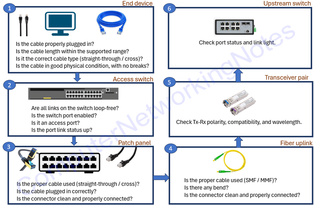
Diagnosing interface and cable issues from an end device to an upstream switch
Conclusion
Ethernet and fiber cables connect end devices in a network. If they have issues, their connected devices fail to connect to the network. Start diagnosing at the host’s NIC and follow the connection through the patch cable, wall outlet, patch panel, switch port, uplink cable, transceiver, and the end device on the other end. This process lets you identify whether the selected medium, cables, termination, switch ports, distance, or signal quality can support a working link before diagnosing and checking configurations on intermediate networking devices such as routers and switches.
Author Laxmi Goswami Updated on 2026-09-29