Wi-Fi Band & Channel Guide: RF Planning & Fixes
Wi-Fi performance depends on far more than access point (AP) placement and raw signal strength. Selecting the correct frequency band and wireless channel is equally critical for maintaining a resilient, low-latency, high-throughput network. Band and channel selection is the deliberate configuration of the radio frequency (RF) band (such as 2.4 GHz or 5 GHz) and the specific frequency index within that band over which APs and client stations communicate. These RF decisions directly dictate cell coverage boundaries, aggregate capacity, co-channel contention, and airtime efficiency. To design and maintain high-performing wireless environments, network engineers must understand the relationship between frequency bands, channel widths, spectral overlap, and half-duplex medium contention.
The following CCNA 2.0 exam objectives are addressed in this tutorial.
1.5 Describe wireless principles
1.5.a Band and channel selection
Table of Contents
1. Demystifying Wi-Fi Frequency Bands and Channels
Unlicensed spectrum allocated for Wi-Fi is divided into distinct frequency ranges known as bands. While enterprise deployments increasingly leverage 6 GHz (Wi-Fi 6E/7), the 2.4 GHz and 5 GHz bands remain the primary operational workhorses across legacy and modern enterprise environments.

Each band is subdivided into individual channels characterized by a designated center frequency and a defined channel width (starting at a base 20 MHz).
   2.4 GHz Band (20 MHz channels, 5 MHz channel spacing):
   [ Ch 1 ]        [ Ch 6 ]        [ Ch 11 ]
   |-------|       |-------|       |-------|
   2.412 GHz       2.437 GHz       2.462 GHz
   (Channels 1, 6, and 11 do not overlap)
1.1 The 2.4 GHz ISM Band: Channelization and Overlap
The 2.4 GHz band operates within the 2.400–2.4835 GHz Industrial, Scientific, and Medical (ISM) spectrum.
Key architectural characteristics include:
- Channel Spacing vs. Channel Width: The band defines up to 14 channel positions spaced just 5 MHz apart. Because standard OFDM channels occupy 20 MHz (and legacy DSSS occupies up to 22 MHz), adjacent channels bleed significantly into one another.
- Regulatory Availability: In the United States (FCC domain), channels 1 through 11 are permitted for standard use. Most ETSI jurisdictions (Europe) permit channels 1 through 13, while channel 14 is heavily restricted (historically limited to 802.11b in Japan).
- Non-Overlapping Triad: In the US regulatory domain, only three 20 MHz channels can operate simultaneously without spectral overlap: Channels 1, 6, and 11.
Assigning non-standard channels—such as channel 3 or channel 8—creates adjacent-channel interference with neighboring cells on both sides, degrading aggregate airtime efficiency.
1.2 The 5 GHz U-NII Band: Architecture and DFS
The 5 GHz spectrum delivers substantially higher channel capacity and reduced contention compared to 2.4 GHz. In the US, the 5 GHz band is divided into four primary Unlicensed National Information Infrastructure (U-NII) sub-bands:
- U-NII-1 (5.150–5.250 GHz): Channels 36, 40, 44, 48 (Indoor-focused, non-DFS).
- U-NII-2A (5.250–5.350 GHz): Channels 52, 56, 60, 64 (Requires DFS).
- U-NII-2C / Extended (5.470–5.725 GHz): Channels 100, 104, 108, 112, 116, 120, 124, 128, 132, 136, 140, 144 (Requires DFS).
- U-NII-3 (5.725–5.850 GHz): Channels 149, 153, 157, 161, 165 (Consumer & enterprise non-DFS).
Unlike the 2.4 GHz band, individual 20 MHz channels in the 5 GHz band do not overlap at their base channelization.
Dynamic Frequency Selection (DFS)
To operate within U-NII-2A and U-NII-2C, APs must support Dynamic Frequency Selection (DFS). If the AP's radio detects radar pulses matching signature profiles (e.g., weather or military radar), it must immediately clear the channel and transition to an alternative non-interfering frequency (Channel Availability Check). This event temporarily disrupts client associations and can dynamically destabilize a manual RF channel reuse plan.
1.3 Channel Aggregation (Channel Bonding)
To deliver higher theoretical data rates, modern 802.11 protocols (802.11n through 802.11be) aggregate contiguous 20 MHz channels into wider transmission swaths:
- 40 MHz: Bonds two 20 MHz channels (1 primary, 1 secondary).
- 80 MHz: Bonds four 20 MHz channels.
- 160 MHz: Bonds eight contiguous (or 8+8 non-contiguous) 20 MHz channels.
   5 GHz Channel Bonding Example:
   [ Ch 36 ] [ Ch 40 ]   [ Ch 44 ] [ Ch 48 ]  <-- 20 MHz channels
   [      40 MHz     ]   [      40 MHz     ]  <-- 40 MHz bonded pairs
   [                  80 MHz               ]  <-- 80 MHz bonded block
Design Caveat: Bonding channels halves the total pool of discrete channels available for frequency reuse. In high-density office spaces, campus lecture halls, and hospitality environments, wide channels (80 MHz or 160 MHz) dramatically increase co-channel contention. For dense enterprise layouts, 20 MHz or 40 MHz channel widths remain the gold standard.
1.4 Half-Duplex Operation and Channel Contention
Wi-Fi uses half-duplex communication over an unguided medium: a transceiver cannot transmit and receive simultaneously on the same channel. To avoid data collisions, Wi-Fi implements Carrier Sense Multiple Access with Collision Avoidance (CSMA/CA) backed by the Clear Channel Assessment (CCA) mechanism.
Before transmitting an 802.11 frame, a station evaluates the physical medium using:
- Preamble Detection (Carrier Sense): Decoding the preamble of valid 802.11 transmissions (typically down to around -82 dBm). If detected, the station updates its Network Allocation Vector (NAV) timer and defers transmission.
- Energy Detection (ED): Measuring raw non-802.11 RF energy across the channel (typically at a higher threshold, approximately -62 dBm).
This arbitration model creates two fundamental interference conditions:
- Co-Channel Interference (CCI) / Co-Channel Contention (CCC): Multiple APs or client devices share the exact same channel within hearing range. Stations detect standard 802.11 preambles, respect virtual carrier sense timers, and defer transmission. While collisions are minimized, channel airtime is split among all competing transmitters, introducing queuing latency and reducing client throughput.
- Adjacent-Channel Interference (ACI): Transmissions occur on partially overlapping or uncoordinated adjacent channels (e.g., AP 1 on Channel 1 and AP 2 on Channel 3). The receiver cannot cleanly decode the overlapping transmitter's preamble. Instead, the overlapping signal acts as unstructured RF noise, raising the noise floor, destroying frame integrity, triggering physical layer errors, and driving high retry rates.
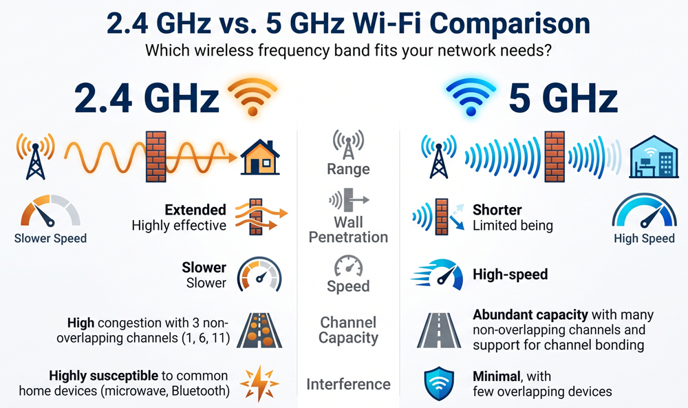
2. RF Characteristics: 2.4 GHz vs. 5 GHz
Selecting the optimal band requires balancing physical attenuation against capacity requirements.
| Metric / Attribute | 2.4 GHz Band | 5 GHz Band |
|---|---|---|
| RF Coverage Radius | Substantially larger coverage footprint. | Smaller coverage footprint due to higher free-space path loss (FSPL). |
| Obstacle Attenuation | Moderate penetration through drywall and wood. | High absorption by concrete, brick, and low-E glass. |
| Available Non-Overlapping Channels | 3 channels (US: 1, 6, 11). | Up to 25 channels (depending on DFS availability). |
| Typical Channel Width | 20 MHz (40 MHz is strongly discouraged). | 20 MHz, 40 MHz, 80 MHz (160 MHz in select profiles). |
| Non-Wi-Fi Interference | Severe (Bluetooth, microwaves, cordless phones, analog cameras). | Minimal (primarily radar systems and fixed-satellite links). |
| Primary Use Case | Legacy devices, IoT, low-bandwidth telemetry, boundary coverage. | High-throughput clients, dense office desks, latency-sensitive traffic. |
Core Objectives of Band and Channel Engineering
- Structured Channel Reuse: Deploying access points in a cellular lattice so that co-channel cells are separated by sufficient physical distance and structural attenuation, preventing cross-cell preamble detection and contention.
- Dynamic Band Steering: Directing dual-band and tri-band client association requests toward 5 GHz (or 6 GHz) via suppressed 2.4 GHz probe responses, reserving the limited 2.4 GHz airtime for single-band legacy and IoT devices.
- Right-Sized Cell Overlap: Ensuring overlapping coverage boundaries sit between -65 dBm and -67 dBm with 15–20% physical overlap for seamless client roaming, while keeping co-channel overlap below -85 dBm.
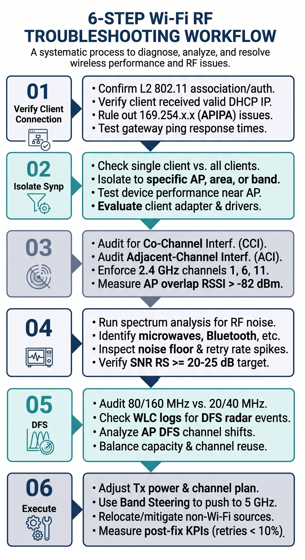
3. Step-by-Step RF Troubleshooting Workflow
When troubleshooting Wi-Fi performance drops, avoid changing AP radio settings blindly. Follow this systematic, six-step RF isolation workflow:
- Step 1: Check L2/L3
- Step 2: Isolate Scope
- Step 3: Analyze ACI/CCI
- Step 4: Check Noise Floor
- Step 5: Inspect DFS/Width
- Step 6: Remediate

Step 1: Verify the Client Connection Boundary
Rule out fundamental Layer 2 and Layer 3 failures before attributing performance issues to RF degradation:
- Confirm complete 802.11 Open/WPA/802.1X association and authentication handshakes.
- Check the client's IPv4 configuration. A self-assigned
169.254.x.x(APIPA) address indicates a DHCP exhaustion or VLAN trunking error—not an RF physical-layer issue. - Confirm that pinging the default gateway shows stable latency before concluding that spectrum congestion is the root cause.
Step 2: Isolate the Symptom Scope
Classify the fault profile into one of four failure modes:
- Single Client, Multiple Locations: Likely a local hardware fault, outdated NIC driver, aggressive roaming profile, or power-save state mismanagement.
- All Clients, One Discrete Area: Points to localized RF shadowing, high attenuation barriers, or co-located non-Wi-Fi interferers.
- All Clients on One Band Only: Clear evidence of localized channel saturation, heavy CCI, or severe non-802.11 interference on that frequency.
- Entire AP Footprint: Suggests uplink duplex mismatch, PoE negotiation issues (forcing the AP into reduced radio chain operation), or hardware failure.
Step 3: Scan the RF Environment for Channel Overlap (ACI and CCI)
Run an enterprise-grade RF scanner (e.g., Ekahau, Hamina, or MetaGeek Wi-Spy) or inspect your Wireless LAN Controller (WLC) Radio Resource Management (RRM) neighbor tables:
- Audit 2.4 GHz Channelization: Verify that every detectable 2.4 GHz AP is locked strictly to 1, 6, or 11. Eliminate off-channel assignments (e.g., 2, 3, 4, 5, 7, 8, 9, 10) to mitigate destructive ACI.
- Measure Co-Channel Signal Overlap: If two APs are sharing Channel 36, check their mutually received RSSI. If AP 2 hears AP 1 at above -82 dBm, their cells are actively contending for airtime and stalling transmissions via CSMA/CA clear-channel delays.
Step 4: Detect Non-Wi-Fi Interference and Noise Floor Spikes
Conventional client utilities only decode valid 802.11 headers. When uncoordinated non-Wi-Fi electromagnetic energy enters the channel, it shows up as an elevated noise floor:
- Use a spectrum analyzer (or hardware-based silicon monitoring like Cisco CleanAir or Aruba RFProtect) to scan raw RF waveforms.
- Microwave Ovens: Emit characteristic sweeping 50/60 Hz pulses across the top half of the 2.4 GHz band (Channels 7–11).
- Signal-to-Noise Ratio (SNR) Analysis: Validate that critical areas maintain an SNR of ≥ 20–25 dB for high-order modulation schemes. An RSSI of -67 dBm against a noisy floor of -80 dBm yields an SNR of only 13 dB, forcing client adapters down to basic modulation (BPSK/QPSK) and triggering packet loss.
Step 5: Audit Channel Width and DFS Radar Logs
If 5 GHz performance degrades unpredictably:
- Inspect Configured Widths: In dense office layouts, identify whether 80 MHz or 160 MHz channels were enabled. Wide channels dramatically raise the noise floor (every doubling of channel bandwidth brings an inherent +3 dB thermal noise penalty) and invite rampant co-channel contention.
- Review WLC Syslogs for Radar Detections: Search for dynamic frequency channel jumps (
Radar detected on channel...). A DFS hit will trigger an immediate channel switch, kicking clients into brief association blackouts and driving downstream co-channel interference on the fallback channel.
Step 6: Implement Remedial Actions and Validate Recovery
Execute corrective interventions, changing only one parameter at a time:
- Standardize Channel Assignments: Enforce channels 1, 6, and 11 on 2.4 GHz. On 5 GHz, assign non-overlapping 20 MHz or 40 MHz blocks suited to your floorplan.
- Optimize AP Transmit Power: Balance AP Effective Isotropic Radiated Power (EIRP) against typical client transmit powers (usually 12–15 dBm / 15–30 mW). Avoid running AP radios at maximum power, which creates asymmetric links where clients hear the AP clearly but lack the transmit power to return frames back to the AP.
- Prune High Channel Widths: Drop wide 80 MHz configurations down to stable 20 MHz or 40 MHz allocations in enterprise multi-AP environments.
- Relocate Physical APs: Shift access points away from metallic ductwork, tinted low-E glass partitions, elevator shafts, and breakroom microwave appliances.
- Validate with Key Performance Indicators (KPIs): Compare pre- and post-remediation metrics:
- Channel utilization under nominal load (target: < 40–50%).
- Layer 2 frame retransmissions / retry rates (target: < 10–12%).
- Ping round-trip latency under loaded airtime.
Conclusion
Band and channel selection is not a "set-and-forget" default—it is the foundational layer of Wi-Fi performance engineering. High signal strength alone cannot overcome a poor channel plan undermined by adjacent-channel overlap, self-induced co-channel contention, or excessive channel widths. By prioritizing strict channel allocation (1/6/11 on 2.4 GHz, right-sized widths on 5 GHz), steering clients away from congested spectrum, and troubleshooting through systematic Layer 1/Layer 2 metrics, network engineers can design and maintain wireless networks that deliver consistent, high-capacity, enterprise-grade connectivity.
Author Laxmi Goswami Updated on 2026-11-07