How to Configure NTP on Cisco Routers
Networking devices maintain independent internal clocks to track time. When devices operate in isolation, time discrepancies do not matter. However, interconnected devices with inconsistent time settings may cause applications that rely on time to malfunction or produce unpredictable results. NTP (Network Time Protocol) allows networking devices to synchronize their time. This tutorial introduces basic concepts and fundamentals of NTP. It explains how to configure, test, and verify NTP on routers using a Packet Tracer example.
Significance of time synchronization
The importance of accurate time synchronization can be illustrated through examples. The following figure shows a network. This network consists of a PC and a Server. A web service is running on the Server. The user on the PC attempts to access the web server and encounters a Certificate is not valid error.

To mitigate security risks like phishing, websites issue digital certificates. Browsers use these certificates to verify the identities of websites. Each certificate is valid for a set period. The browser relies on the local system’s time to authenticate the certificate. If there is a significant gap between the certificate’s validity and system time, the browser will not validate the certificate. It will display a warning message to the user. This issue can be fixed by updating the time settings.
Let us take another example. The Sales section of a company opens at 7.00 AM and closes at 7.00 PM. The company wants to allow users to access its server only in business hours. So it configured a time-based firewall on the router that connects users to the server. The router’s clock is 12 hours ahead of the server’s.

Due to this configuration error, users will be unable to log in to the server during working hours. A router uses its own clock to authenticate the access. With this setup, the router allows users to log in between 7.00 PM and 7.00 AM, rather than 7.00 AM to 7.00 PM.
The above examples show the importance of accurate time synchronization and configurations. NTP is a dedicated protocol for time synchronization. It allows you to configure and use a centralized time for all your networking devices.
NTP configuration on routers
A router can be configured in one of the following three modes.
- NTP Server only
- NTP Server /Client
- NTP Client only

NTP Server Mode
In this mode, a router reads time from an NTP source. Unless you manually define the NTP source, a router uses its own clock as the NTP source. As per requirements, you can configure the router’s clock or use an external clock as the NTP source. Once the NTP source is configured, the NTP server router advertises the time in the network. In this mode, the router only advertises NTP updates. It doesn’t accept NTP updates from other NTP servers.
NTP Server/Client Mode
In this mode, a router receives updates from the NTP server and advertises them from its own interfaces. This way, the router plays both roles. As an NTP client, it receives NTP updates, and as an NTP server, it advertises them.
In this mode, as an NTP server, a router advertises the NTP updates it receives from another NTP server. This feature allows you to configure a single centralized NTP source at the NTP server.
NTP Client Mode
In this mode, a router only receives NTP updates. It does not advertise received updates. It uses them to sync its own clock.
NTP configuration (Lab setup)
Set up a practice lab as shown in the following image. You can use a network simulator software or real devices to set up this lab. The commands and configuration steps are the same on all platforms. However, the commands to configure NTP are not available on all simulator software. For example, these commands are not available on Packet Tracer. Packet Tracer is one of the most popular and widely used network simulation software tools for configuring and testing essential Cisco devices for Cisco certification programs. It uses stripped-down versions of Cisco IOS image files to simulate Cisco devices.

This tutorial uses GNS3. GNS3 is an open-source network simulator software. It allows you to simulate/emulate Cisco devices with the original Cisco IOS image files. The following tutorial explains how to install and set it up on a Windows system.
Learn how to install and configure GNS3 for CCNA lab
Initial IP configurations
Assign the following initial IP configurations and enable routing on all routers.
| Router | Interface | IP address | Connected With |
| R1 | Serial 0/0 (DCE) | 10.0.0.1/24 | Serial 0/0 (R2) |
| R1 | Serial 0/1 (DCE) | 20.0.0.1/24 | Serial 0/1 (R2) |
| R2 | Serial 0/0 (DTE) | 10.0.0.2/24 | Serial 0/0 (R1) |
| R2 | Serial 0/1 (DTE) | 20.0.0.2/24 | Serial 0/1 (R1) |
| R2 | Serial 0/2 (DCE) | 30.0.0.2/24 | Serial 0/2 (R3) |
| R2 | Serial 0/3 (DCE) | 40.0.0.2/24 | Serial 0/3 (R4) |
| R3 | Serial 0/2 (DTE) | 30.0.0.1/24 | Serial 0/2 (R2) |
| R4 | Serial 0/3 (DTE) | 40.0.0.1/24 | Serial 0/3 (R2) |
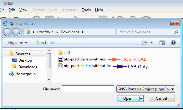
Alternatively, you can download the lab used in this tutorial from the following links. It includes all initial configurations. This lab is built with Cisco 2600 series routers. By default, GNS3 does not include Cisco IOS image files. To emulate/simulate a Cisco device in GNS3, you must provide its IOS image file. If your GNS3 has this router, use the first link. If not, use the second link. It provides the practice lab and the IOS image file of the router used to build it.
Importing NTP practice LAB in GNS3
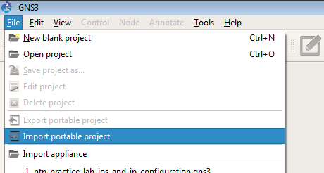
Open GNS3, click the File menu, and select Import portable project.
Select the downloaded file.
Choose a descriptive name for the project, select the folder location where you want to save this project, and click Save.

Once the practice lab is imported, click the Start button to start the LAB.

NTP Stratum
NTP devices obtain time from an NTP source. The stratum value indicates the reliability and accuracy of this source, with a scale from 0 to 15. Stratum 0 represents the most reliable time source, while stratum 15 is the least reliable.
Stratum-0 devices utilize atomic clocks and provide the highest level of time accuracy. Accessing time from these devices requires significant CPU and memory resources. Consequently, stratum-0 devices are typically deployed in critical sectors such as defense, research, space, and meteorological departments.
Due to the high resource requirements for synchronizing with stratum-0 devices, standard computers and networking equipment, including Cisco routers, do not synchronize directly with these sources. Regular Cisco routers cannot be configured to use stratum-0 time.
Public time servers, classified as stratum-1 devices, synchronize their clocks with stratum-0 devices and provide optimized time for general use. Accessing time from stratum-1 servers does not require additional CPU or memory resources, making it suitable for standard devices, including Cisco routers.
In practice, organizations typically deploy a dedicated NTP server that obtains time from a stratum-1 server. This dedicated NTP server then serves as the centralized time source for the entire network.
The NTP configuration steps are the same regardless of the chosen time source.
NTP server configuration
Deploying a router as a NAT server requires the following steps.
- Adjusting router clock
- Configuring a Loopback interface
- Adding the loopback interface’s network address to the routing table
- Configuring the NTP server
- Configuring active interfaces to act as an NTP server only
Adjusting the router clock
Right-click R1 and click Console to open its command prompt.

Run the show clock command to display the current time, date, and the configured time zone.
R1#show clock
*00:15:05.392 UTC Fri Mar 1 2002
If the output of this command shows incorrect time, date, or time zone, update it before using it as the NTP source. The following commands allow you to manage time and related settings.
| Command | Mode | Description |
| R1(config)#clock timezone [Keyword] [value] | Global configuration mode | Set the time zone |
| R1(config)#clock summer-time [Keyword] [value] | Global | configuration mode Set the daylight saving time |
| R1#set clock [h:m:s] [DD MM yyyy] | Privilege Exec mode | Set the date and time |
R1#configure terminal
R1(config)#clock timezone EST -5
R1(config)#clock summer-time EDT recurring
R1(config)#exit
R1#clock set 18:45:26 5 April 2026
R1#show clock
The first command enters global configuration mode.
By default, a router uses the universal time zone. The second command allows you to localize the time zone. It accepts the following two parameters.
Keyword [EST]
This parameter lets you assign a descriptive name to your time zone. The router will not use it to calculate the time. It will display the name you set here in the time zone field. Although you can use any name here, select a name that reflects your time zone. For example, EST (US Eastern Standard Time), IST (Indian Standard Time), CST (Central Standard Time), etc.
Value [-5]
The router uses this parameter to calculate the time offset from UTC (Universal Time Coordinated). The '-5' value in this field indicates that the system’s time zone is 5 hours behind UTC.
The third command lets you adjust the 'daylight saving time'. Like the second command, it accepts the following two parameters.
Keyword [EDT]
Similar to the previous command, set a descriptive name for daylight saving time. Set a name that reflects daylight saving time in your time zone, such as EDT (Eastern Daylight Time).
Value [recurring]
The router uses this parameter to take the appropriate action during "daylight saving time." The recurring value tells the router to spring forward an hour and fall back an hour automatically each year.
DST (Daylight Saving Time)
DST (Daylight Saving Time) is a concept that aims to better utilize natural daylight. In this concept, clocks are moved forward one hour from standard time in the spring and set back one hour in the autumn. This command is optional. If your network does not use it, you can skip this command.
The fourth command exits global configuration mode.
The fifth command sets the date and time. In this command: -
Time in HH:MM:SS [18:45:26]
This parameter sets the time in 24-hour format (hours:minutes:seconds).
Date in DD:MM:YYYY [5 April 2026]
This parameter sets the date.
The sixth command verifies that the date, time, and time zone are updated correctly.

Configuring the Loopback interface
Although NTP allows you to use any interface for the NTP Server reference, always use the loopback interface for this purpose. A physical interface can go down for several reasons, but the loopback interface remains up until you manually shut it down. Let’s create a loopback interface in R1.
| Command | Description |
| R1#configure terminal | Enter global configuration mode |
| R1(config)#interface loopback 0 | Create a loopback interface |
| R1(config)#ip address 100.0.0.1 255.255.255.0 | Assign an IP address to this interface |
| R1(config)#no shutdown | Bring the interface up |
| R1(config)#exit | Exit the interface |

Adding routing information for the loopback interface
Unless you add the loopback interface’s network address to the routing updates of the configured routing protocol, other devices cannot connect to it. This lab uses the RIP routing protocol. Use the following commands to add the loopback interface’s network address.
R1#router rip
R1(config-router)#network 100.0.0.0
R1(config-router)#exit

Configure NTP Server
NTP server configuration is straightforward. It takes only two commands to deploy a router as an NTP Server.
Router(config)#ntp master [stratum level]
Router(config)#ntp source [Interface / hostname or IP address of NTP Source]
In the first command, the stratum level is optional. If you do not specify it, the router will use the default value. The default stratum level of the router’s internal clock is 7.
In the second command, you have to specify the NTP source. You can use any valid NTP source here.
- To use a public NTP server, type its IP address here. To use a public NTP server, the router must be connected to the Internet, and UDP port 123 must be allowed in the firewall.
- To use another NTP server from the internal network, type the IP address of that server.
- To use the router's internal clock, use any configured IP address on any interface.
This lab uses R1’s internal clock as an NTP source. To use a router’s internal clock as the NTP source, use the IP address configured on any of its interfaces. The only benefit of using the loopback interface’s IP address instead of a physical interface’s IP address is that the loopback interface always remains on.

Configuring NTP master
By default, the router works in the NTP Server/client mode. In this mode, the router advertises and listens to NTP broadcasts from all active interfaces. To deploy this router as an NTP Server only, configure all active interfaces only to broadcast NTP messages. The following command does this. Run this command in the interface configuration mode of all active interfaces.
Router(config-if)#ntp broadcast
R1 has two active interfaces. Configure them only to broadcast the NTP messages.

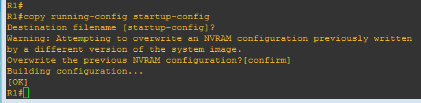
Save the running configuration.
R1#copy running-config startup-config
Configuring NTP Server/Client
This is the default mode. No additional configuration is required to deploy a router in this mode. However, in this mode, a router uses its own clock as the NTP source. To build a hierarchy in which this router receives time from another NTP server, set its NTP source. Use the following command to change the NTP source.
Router(config)#ntp server [NTP Source IP Address]
This lab uses R1 as the main NTP server. To deploy R2 in NTP Server/Client mode, which reads time from R1, use the following command on R2.
R2(config)#ntp server 100.0.0.1

The synchronization process may take a few minutes at first. However, once it is done, the clock is updated automatically.
Configuring NTP Client
To configure a router as the NTP client, use the following commands.
Router(config)#ntp server [NTP Server IP address]
Router(config-if)#ntp broadcast client

The first command forces the router to use the NTP server time instead of its own local time. The second command configures the active interface to listen only for the NTP broadcast messages.
Configure R3 and R4 as NTP clients. You can use any configured IP address on the NTP server router to receive NTP updates. Use the R2’s serial interface’s IP address to connect to the NTP server.
NTP client configuration on R3

NTP client configuration on R4

Verifying the NTP setup
You can verify the NTP setup using the two show commands: ntp status and ntp associations.
The show ntp status command
The first line of the output of this command provides all the information you need to verify your NTP setup. It contains three columns: clock status, stratum level, and NTP source.
Clock status
This column indicates whether the clock is synchronized. If you have just configured the router and the show clock command is not displaying the updated time, check this column. The updated time will be displayed only when the clock is synchronized.
Stratum level
This column shows the router’s time on the reliability scale after the synchronization. If the router is not connected to any NTP server or the clock is not synchronized with any NTP source, this column will always show the value 16. If the router is synchronized with an NTP source, this column displays the router's stratum level in the NTP hierarchy. Usually, it remains one level down from the NTP source unless it is modified manually.
Key points:-
- Stratum 0 represents an atomic clock and is not used on Cisco routers.
- Stratum 1-15 are valid levels and used on Cisco routers. 1 is the most reliable, and 15 is the worst NTP source.
- Stratum 16 indicates that the router is either not connected to any NTP source or not yet synchronized with any NTP server.
- By default, after synchronization, the router keeps its time one level down from the NTP source or server. It allows us to build a proper hierarchy.
- The default stratum level of the router’s internal clock is 7.
NTP source
This column shows the source or reference of the NTP source from which this time is synchronized.

The show ntp associations command
This command provides information about the NTP server address, NTP source clock, and the stratum level.

- The address column may contain two additional symbols: * and ~. The * shows NTP mode in which NTP server is working and ~ shows how NTP is getting time from NTP source.
- The ref column clock shows the NTP source from which the NTP server received the time.
- The st column shows the stratum level of the NTP source.
Conclusion
Accurate time synchronization is essential for the proper functioning and security of networked devices. This tutorial has demonstrated the significance of NTP, outlined its configuration in various modes, and provided practical steps for deploying and verifying NTP in a simulated lab environment. By implementing NTP correctly, organizations can ensure consistent timekeeping across all network devices, helping prevent errors, supporting security protocols, and simplifying network management.
Author Laxmi Goswami Updated on 2026-04-27