How to use GNS3, GNS3 Terminology, and Overview
GNS3 allows you to test network topologies in a virtual environment. This tutorial provides an overview of the GNS3 interface and explains the steps you need to create and test topologies in GNS3.
A project is your network. When you create a new project or network, GNS3 creates a blank project. It does not add any devices. After making a blank project, you can add any available device to it. To create a new blank project, click File, and click New blank project.

Set the project name and location, then click OK.

Overview / Introduction to GNS3 GUI

| GNS3 workspace | The area where you create the network by adding devices and links. |
| GNS3 Toolbar | Contain the group of icons that allow you to perform common tasks. |
| Device Toolbar | Contain devices that you can add to your network. |
| Topology Summary pane | List all devices that you are using in the current network topology. |
| Server Summary pane | Show the status of the local server and GNS3-VM (if in use). |
| Console pane | Show errors and logs GNS3 encounters while executing tasks. |
Adding devices to the network
Currently, this network has no devices. To use it, you need to add the necessary devices. GNS3 supports two types of devices: emulated and simulated. The default GNS3 installation includes only simulated devices. To use emulated devices, you must first import them.
Let's build and test a simple network that contains two PCs and an Ethernet switch. To create this network, add the PCs and the Ethernet switch to the workspace. To add a device to the network, select the device from the device toolbar, then drag it to the workspace. To unselect an option chosen on the device toolbar, click it or close the opened subpane.
The following image shows the process of adding two virtual computers to the network.

The following image shows the process of adding an Ethernet switch to the network.

Connecting devices
To connect devices, click Add a Link. The mouse pointer will change into a plus sign. Click the first device (PC1). The device will display all available interfaces. Select the interface you want to use to connect this device to another device. Click the second device (Switch1) and select the interface you want to use to connect to the first device (PC1).
The following image shows how to connect the PCs to the Ethernet switch.

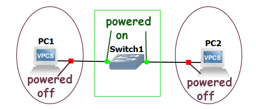
GNS3 adds PCs in the powered-off state while it adds switches in the powered-on state. To show the state of a device, it uses three different colors.
| Color | State |
| Red | Powered off |
| Green | Powered on |
| Yellow | Suspended |
GNS3 does not use a color indicator for the interface state. To check an interface's state, examine the device's running configuration. To change the device's state, select the device, then right-click it. In the right-click context menu, you can change the device's state. To change the state of all devices in the workspace, use the options available on the GNS3 toolbar.

Labeling/showing interface names
By default, GNS3 does not display interface names. To show interface names, click Show/hide interface labels. It toggles the current state. For example, if interface names are visible, clicking will hide them. If they are invisible, clicking will show them. You can also add notes. To add a note, click Add a note. The following image shows how to show and hide interface names and add a note.

Configuring a device
GNS3 does not provide a graphical utility to configure devices. To configure a device, you have to use the console prompt. To open the console prompt of a device, right-click the device and click Console. To open the console prompt of all devices, click Console on the GNS3 toolbar.

Assigning an IP address
To assign an IP address to the PC, use the following command.
ip [IP address] [Subnet mask]
GNS3 checks the supplied IP address on the network. If the provided IP is not in use, it assigns the IP address. The following image shows the process of assigning IP addresses to PC1 and PC2.

Verifying connectivity
To test device connectivity, use the ping command. The ping command sends small test data packets to the destination device in a sequence. If the destination device is up and reachable, it replies to these data packets. If you see reply messages in the output of this command, it verifies that the source and destination devices are correctly connected.

Saving configuration
By default, GNS3 does not save the device's running configuration. It means if you reload the project or device, the running configuration on the device will be lost. To save the running configuration on the device, use the device's save function. To save the running configuration on a PC, use the save command.

Use the save command to save the running configuration on all PCs. If you save the project after saving the running configuration on all PCs, on reload, all PCs will start from where you left them.
This tutorial is part of the tutorial "Installing, Configuring, and Managing Packet Tracer and GNS3". Other parts of this tutorial are as follows:
Chapter 01 How to install and activate Packet Tracer in Windows
Chapter 02 How to install and start Packet Tracer in Ubuntu
Chapter 03 Difference between emulation and simulation
Chapter 04 Differences between Packet Tracer, GNS3, and Cisco VIRL
Chapter 05 What are GNS3-all-in-one and GNS3
Chapter 06 GNS3 Setup Wizard Options Explained
Chapter 07 How to Install GNS3 Explained
Chapter 08 GNS3 Terminology and Overview
Chapter 09 How to Import IOS in GNS3
Conclusion
GNS3 is a powerful tool for simulating network topologies and testing various configurations in a virtual environment. By following the steps outlined in this tutorial, you can effectively create new projects, add devices, connect them, and configure their settings. Whether you are a beginner or an experienced network engineer, GNS3 serves as an invaluable resource for network design and testing.
Author Laxmi Goswami Updated on 2025-10-30