OSPF DR BDR Selection Process Explained
OSPF routers share routing information differently on different network types. This tutorial explains how they share it on an Ethernet broadcast network. On an Ethernet broadcast network, they first elect a DR (Designated Router) and a BDR (backup Designated Router) and then share routing information via them.
On each Ethernet broadcast segment, OSPF implements a client/server design. In this design, a router called DR acts as a server. The server is responsible for keeping and providing updated routing information. If a client has updated routing information, it shares that with the server. The server updates its database and shares that with other clients.
Since the DR plays a lead role in how the database exchange process works, OSPF implements an additional router as a backup for the server. This router is called BDR. A BDR maintains the same routing information as the DR. If the DR fails, it immediately becomes the DR, acting as a hot standby. Apart from the DR and BDR, all remaining routers are considered clients. They are known as DROTHERs.

OSPF routers select a DR and a BDR for every Ethernet broadcast segment. For example, if you have twenty VLANs in your switched area, you'll have twenty DRs and twenty BDRs. An OSPF router talks to a DR using the IP multicast address 224.0.0.6. The DR and the BDR talk to all OSPF routers using the 224.0.0.5 multicast IP address.
DR and BDR Election Process Criteria
OSPF routers use OSPF priority and RID to elect a DR and BDR. The router with the highest OSPF priority on a segment becomes the DR for that segment. The router with the second-highest priority becomes the BDR for that segment. If you do not change the default priority, routers use RID to elect a DR and a BDR. The router with the highest RID becomes the DR. The router with the second-highest RID becomes the BDR. All other routers become DROTHERs.
DR and BDR Election Process Example
Create a practice lab, as shown in the following image, and enable OSPF processes on all routers.

Download the Packet Tracer practice lab with IP configurations.
Enabling the OSPF process
Use the following commands to enable OSPF processes.
R1
Router>enable
Router#configure terminal
Router(config)#router ospf 1
Router(config-router)#network 192.168.1.0 0.0.0.255 area 0
Router(config-router)#network 10.0.0.0 0.255.255.255 area 0
Router(config-router)#exit
Router(config)#exit
Router#

R2
Router>enable
Router#configure terminal
Router(config)#router ospf 1
Router(config-router)#network 192.168.1.0 0.0.0.255 area 0
Router(config-router)#network 20.0.0.0 0.255.255.255 area 0
Router(config-router)#exit
Router(config)#exit
Router#

R3
Router>enable
Router#configure terminal
Router(config)#router ospf 1
Router(config-router)#network 192.168.1.0 0.0.0.255 area 0
Router(config-router)#network 30.0.0.0 0.255.255.255 area 0
Router(config-router)#exit
Router(config)#exit
Router#

R4
Router>enable
Router#configure terminal
Router(config)#router ospf 1
Router(config-router)#network 192.168.1.0 0.0.0.255 area 0
Router(config-router)#network 40.0.0.0 0.255.255.255 area 0
Router(config-router)#exit
Router(config)#exit
Router#

Download the Packet Tracer practice lab with OSPF configurations.
RID
Since you did not change the default priority on any router, routers will use the RID to elect a DR and BDR. A router uses the following options in a sequence to select an RID. If it finds a value in an option, it does not check the next option. It checks the following option when it does not see a value in the current option.
- Custom RID value configured by using the router-id command.
- The highest IP address among all IP addresses configured on loopback interfaces.
- The highest IP address among all IP addresses configured on physical interfaces.
Since you did not configure a custom RID and loopback interfaces on any router, all routers will use the highest IP address among all IP addresses configured on physical interfaces to select their RIDs.

After selecting RIDs, OSPF routers select a DR and a BDR for each broadcast segment. Since all routers have a default OSPF priority ID, they use their RIDs to select the DR and BDR. The router with the highest RID becomes the DR. The router with the second-highest RID becomes the BDR. The remaining routers become DROTHERs.

Verifying the DR and BDR election
The show ip ospf neighbor command lists all OSPF neighbors. The output of this command has the following six fields.
| Field | Description |
| Neighbor ID | The RID of the neighbor |
| Pri | OSPF priority of the neighbor |
| State | Routing information exchange state / Router's role |
| Dead Time | Dead interval |
| Address | IP address of the neighbor |
| Interface | Local interface connected to the neighbor |
You can use the State field to verify the DR and BDR election process. It displays the routing information exchange state and the router's role in the segment.
The following image shows the output of this command on R1.

The following image shows the output of this command on R2.

The following image shows the output of this command on R3.

The following image shows the output of this command on R4.

Influencing the DR and BDR selection process
You can manipulate the DR and BDR selection process by changing the OSPF priority. The following command changes the default OSPF priority.
Router(config-if)#ip ospf priority [value]
You can set any value between 0 and 255. The default value is one. The router with the value zero never becomes a DR or BDR. The router with the highest priority value becomes the DR. The router with the second-highest priority value becomes the BDR. In this example network, currently, routers have the following roles.
R4 is DR, R3 is BDR, R2 and R1 are DROTHERs.
Now, suppose you want to configure R1 as DR, R2 as BDR, and R3 and R4 as DROTHERs. For this, you need to change the default OSPF priority on R1 and R2. You need to change the R1's OSPF priority to be higher than all other routers. You need to change the R2's OSPF priority to be higher than R3 and R4 but less than R1. You can keep the default priority on R3 and R4 or change it to zero. A router with priority zero always becomes a DROTHER.
Changing default priority
OSPF runs processes on an interface basis. You can use a different OSPF priority on all interfaces. You must change the default priority on the interface connected to the broadcast segment to influence the DR and BDR selection process. In this example network, the Fa0/0 interface on all routers is connected to the broadcast network. You need to change the default OSPF priority on this interface.
R1
Router(config)#interface fastethernet 0/0
Router(config-if)#ip ospf priority 4
Router(config-if)#exit
Router(config)#exit
Router#

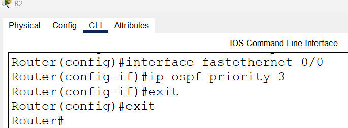
R2
Router(config)#interface fastethernet 0/0
Router(config-if)#ip ospf priority 3
Router(config-if)#exit
Router(config)#exit
Router#
R3
You configured OSPF priority three on R2 and four on R1. If you do not change the OSPF priority on this router, the router will use the default priority. As you know, the default OSPF priority is one. One is less than three and four. With default priority, it will become DROTHER.
R4
With the current configuration, this router is DR. To make it a DROTHER, you can change its priority to zero. A router with priority zero always becomes a DROTHER.
Router(config)#interface fastethernet 0/0
Router(config-if)#ip ospf priority 0
Router(config-if)#exit
Router(config)#exit
Router#

Download the Packet Tracer practice lab with manipulated OSPF priority.
Verifying the DR and BDR selection process
You can use the show ip ospf neighbor command again on all routers to verify how the OSPF priority value manipulates the DR and BDR selection process.
The following image shows the output of this command on R1.

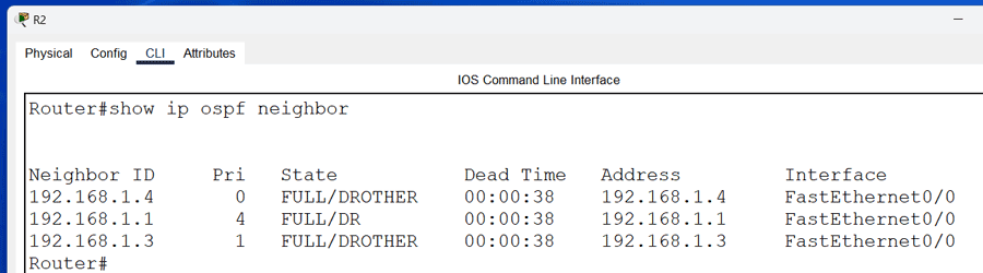
The following image shows the output of this command on R2.
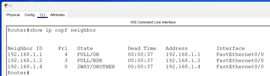
The following image shows the output of this command on R3.
The following image shows the output of this command on R4.

As the above output shows, now, R1 is the DR, R2 is the BDR, and R3 and R4 are DROTHERs on the network. This way, by changing the default OSPF priority, you can prompt any router as the DR, BDR, or DROTHER.
This tutorial is part of the tutorial "OSPF Configuration and Concepts Explained.". Other parts of this tutorial are as follows:
Chapter 01 OSPF (Open Shortest Path First) Protocol
Chapter 02 RIP V/s OSPF | Differences between RIP and OSPF
Chapter 03 IGP, EGP, and Autonomous System Explained
Chapter 04 OSPF Features, Advantages, Disadvantages
Chapter 05 OSPF Fundamental Terminology Explained
Chapter 06 OSPF LSA Types and LSA Flooding Explained
Chapter 07 OSPF Area Types and Concept Explained
Chapter 08 OSPF Hello Protocol and Packets Explained
Chapter 09 OSPF RID (Router ID) Explained
Chapter 10 OSPF Neighborship Condition and Requirement
Chapter 11 OSPF DR BDR Selection Process Explained
Chapter 12 How OSPF Routers Build Adjacency Explained
Chapter 13 Shortest Path First (SPF) Algorithm Explained
Chapter 14 OSPF Single-Area Configuration Explained
Chapter 15 OSPF Stub area, Totally Stub area, NSSA, and Totally NSSA
Chapter 16 OSPF Virtual Links Explained
Chapter 17 OSPF Authentication Password and MD5 Explained
Chapter 18 OSPF Multi-Area Configuration Explained
Conclusion
On an Ethernet network, OSPF uses DR/BDR to share routing information. This tutorial explains how OSPF selects a DR and BDR and what criteria it uses in the selection process. Learning this process and its components helps you to customize this process and force OSPF to select particular routers as DR and BDR.
By ComputerNetworkingNotes Updated on 2026-05-04