VLAN Practice Lab Setup in Packet Tracer
Packet Tracer is a network simulator software. It allows you to create and test network topology in a simulated environment. You can use it to practice VLAN-related topics.
VLAN is a switch feature. To practice VLAN-related topics, you need to set up a practice lab. The minimum requirement for a practice lab is one switch, one router, and two PCs. Routers and switches are costly. Purchasing routers and switches to set up a practice lab is not possible for everyone. Network simulator software solves this problem by simulating networking devices. They allow you to create a practice lab in a simulated environment. Packet Tracer is a network simulator software. It allows you to simulate essential networking devices.
Setting up a VLAN practice LAB on Packet Tracer
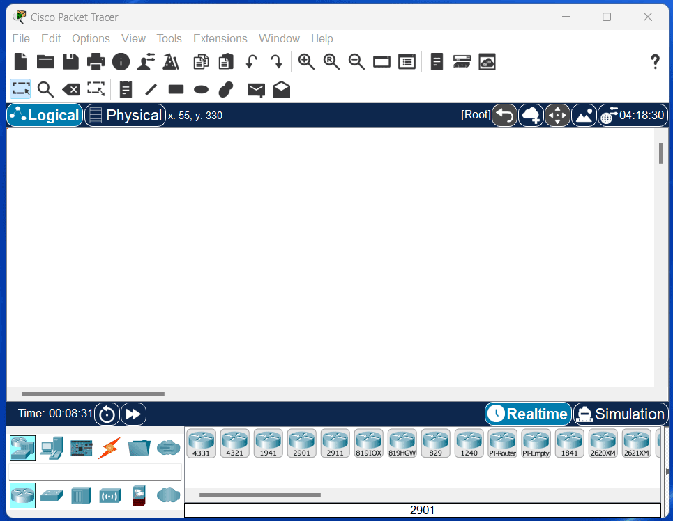
Start Packet Tracer. The following image shows Packet Tracer's interface.
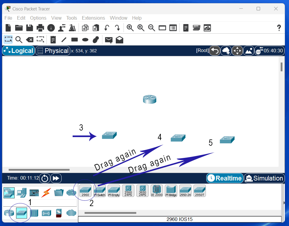
Drag a router to the workspace. You need it to provide inter-VLAN connectivity. You can choose any router.

Drag and add three switches to the workspace. You will configure VLANs on these switches. Although you need only one switch to configure and test the basic features of VLANs, three switches allow you to configure and test the extended features of VLANs.
Drag and add six PCs to the workspace. You will connect two PCs to each switch. A VLAN is a logical group of devices. You can add any device connected to the switch to any VLAN. For example, you can create two VLANs and keep three PCs in each VLAN, one from each switch.

After adding the necessary devices, you must connect them. Use a straight-through cable to connect a router to a switch and a switch to a PC. Use a cross-over cable to connect a switch to another switch. Connect the Router to S1's GigabitEthernet0/1.

Connect S1's GigabitEthernet0/2 to S2's GigabitEthernet0/2 and S2's GigabitEthernet0/1 to S3's GigabitEthernet0/1.

Connect S1's FastEthernet 0/1 to PC0 and FastEthernet 0/2 to PC1, PC2, and PC3 to S2's FastEthernet 0/1 and 0/2, and PC4 and PC5 to S3's FastEthernet 0/1 and 0/2.

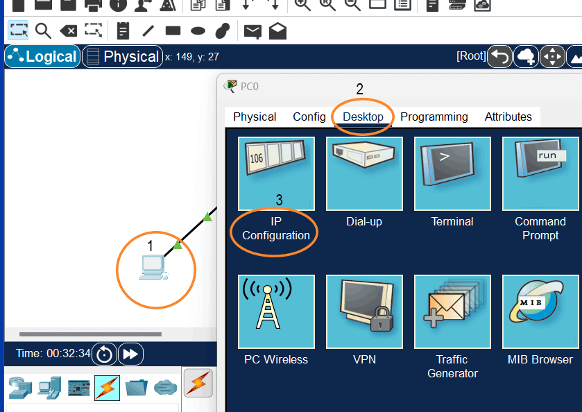
Finally, assign an IP configuration to each end device. Each VLAN belongs to a separate IP subnet. In this lab, you will configure two VLANs. For two VLANs, you need two IP subnets. You can use any IP subnets. This tutorial uses 10.0.0.0/8 and 20.0.0.0/8. Assign IP configurations to end devices. To assign an IP configuration, click PC, click Desktop, and click IP configuration.
Assign an IP configuration from the first IP subnet.

Repeat the same process and assign an IP configuration from the second IP subnet to the second PC connected to S1.

The following image shows the IP configuration on all PCs.

Use the same gateway IP address on PCs belonging to the same VLAN.
This tutorial is part of the tutorial VLAN, VTP, and DTP Concepts and Configurations on Cisco Routers.. Other parts of this tutorial are as follows:
Chapter 01 VLAN Basic Concepts Explained with Examples
Chapter 02 Advantages and Disadvantages of VLANs
Chapter 03 Static and Dynamic VLAN Membership Explained
Chapter 04 Access Link and Trunk Link Explained
Chapter 05 VLAN Tagging Explained with DTP Protocol
Chapter 06 DTP Modes and Protocol Explained
Chapter 07 802.1Q Native VLAN concept Explained
Chapter 08 Cisco Inter-Switch Link (ISL) Explained
Chapter 09 Trunk Tagging and Frame Tagging Explained
Chapter 10 VTP Modes and VTP Protocol Explained
Chapter 11 VTP Pruning on switches Explained
Chapter 12 VLAN Practice Lab Setup in Packet Tracer
Chapter 13 Configure VTP Server and Client in Switch
Chapter 14 VLAN Configuration Commands Step by Step Explained
Chapter 15 Router on Stick Configuration Explained
Conclusion
Packet Tracer is a network simulator software. This tutorial explained the steps to set up a practice for VLAN configuration. This tutorial is part of a tutorial series. The following parts of this series use this lab to explain VLAN configuration.
Author Laxmi Goswami Updated on 2026-04-19